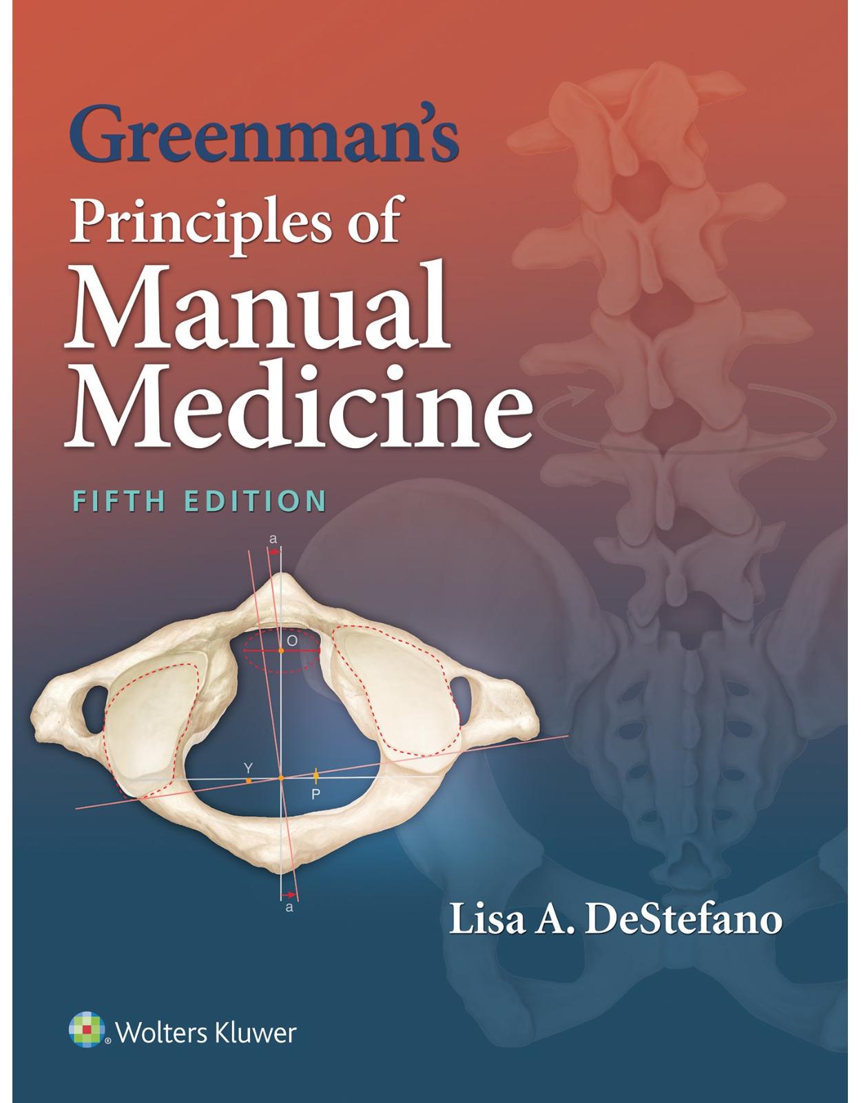
Greenman's Principles of Manual Medicine
Livrare gratis la comenzi peste 500 RON. Pentru celelalte comenzi livrarea este 20 RON.
Disponibilitate: La comanda in aproximativ 4 saptamani
Autor: Lisa A. DeStefano
Editura: LWW
Limba: Engleza
Nr. pagini: 520
Coperta: Paperback
Dimensiuni: 21.08 x 2.29 x 27.43 cm
An aparitie: 1 Mar. 2016
Description:
With a focus on the “how” and “why” of manual medicine techniques, Greenman’s Principles of Manual Medicine, Fifth Edition, gives you the tools you need to improve patients’ neuromusculoskeletal system function. Covering the foundations of manual medicine as well as specific techniques for diagnosing and treating musculoskeletal pain, this popular guide features more than 1,000 photographs that walk you step by step through each technique. Taking you systematically from principles and concepts, through specific techniques and procedures, to clinical correlations, this new edition is thoroughly up to date, and features a clinical focus that prepares you for today’s practice.
Table of contents:
Part I: PRINCIPLES AND CONCEPTS
1: Structural Diagnosis and Manipulative Medicine History
HISTORY
Osteopathic Medicine
Chiropractic
MEDICAL MANIPULATORS
PRACTICE OF MANUAL MEDICINE
GOAL OF MANIPULATION
ROLE OF THE MUSCULOSKELETAL SYSTEM IN HEALTH AND DISEASE
Concept of Holism
Concept of Neural Control
Figure 1.1: Cross section of spinal cord segment.
Figure 1.2: Autonomic nerve distribution.
Circulatory Function
Figure 1.3: The cellular milieu.
Figure 1.4: Thoracoabdominal diaphragm.
Figure 1.5: Lymphatic system.
Energy Expenditure
Self-Regulation
THE MANIPULABLE LESION
DIAGNOSTIC TRIAD FOR SOMATIC DYSFUNCTION
Suggested Readings
References
2: Principles of Structural Diagnosis
HAND–EYE COORDINATION
Figure 2.1: Test for dominant eye.
LAYER PALPATION
Figure 2.2: Layer palpation of dorsal forearm.
Figure 2.3: Layer palpation of volar forearm.
Figure 2.4: Palpation of musculotendinous junction.
Figure 2.5: Palpation of transcarpal ligament.
Figure 2.6: Palpation of radial head.
Vertebral Column Muscles
Figure 2.7: Layer palpation of shawl area.
Figure 2.8: Skin motion on subcutaneous fascia.
Figure 2.9: Skin rolling.
Figure 2.10: Palpation of shoulder girdle and coracoid process.
Figure 2.11: Layer palpation of trapezius muscle.
Figure 2.12: Layer palpation of rhomboid muscle.
MOTION SENSE
Motion Sense Palpatory Exercise
Figure 2.13: Layer palpation of the spinous processes.
Figure 2.14: Palpation of the interspinous spaces during forward bending.
Figure 2.15: Palpation of the interspinous spaces during backward bending.
Figure 2.16: Palpation of the medial groove erector spinae muscles.
Figure 2.17: Palpation of the lateral groove erector spinae muscles.
Figure 2.18: Palpation of transverse processes.
Figure 2.19: Palpation of the rib angles and iliocostalis muscle.
Figure 2.20: Palpation of rib angle contour.
Figure 2.21: Palpation of rib shaft to tip of transverse process.
Hypermobility
SUMMARY
SCANNING EXAMINATION
SEGMENTAL DEFINITION
SCREENING EXAMINATION
STEP 1. GAIT ANALYSIS
Figure 2.22: Observation of gait from the front.
Figure 2.23: Observation of gait from the back.
Figure 2.24: Observation of gait from the right side.
Figure 2.25: Observation of gait from the left side.
STEP 2A. STATIC POSTURE ANALYSIS
Figure 2.26: Static analysis of the front.
Figure 2.27: Static analysis of the back.
Figure 2.28: Static analysis of the right side.
Figure 2.29: Static analysis of the left side.
STEP 2B. STATIC POSTURE ANATOMIC LEVELS
Figure 2.30: Observation of the levels of the acromion process.
Figure 2.31: Palpation and observation of the top of the iliac crests.
Figure 2.32: Palpation and observation of the top of the greater trochanters.
STEP 3. TRUNK SIDE BENDING
Figure 2.33: Observation of left trunk side bending from the back.
Figure 2.34: Observation of right trunk side bending from the back.
STEP 4. STANDING FLEXION TEST
Figure 2.35: Palpation of the inferior slope of the posterior superior iliac spines.
Figure 2.36: Standing flexion test.
CLINICAL PEARL
STEP 5. STORK TEST
Figure 2.37: Preparation for left stork test; left thumb on the inferior slope of the left posterior superior iliac spine, right thumb midline at same level.
Figure 2.38: Left stork test.
Figure 2.39: Right stork test.
CLINICAL PEARL
STEP 6. SEATED FLEXION TEST
Figure 2.40: Preparation for seated flexion test; thumbs placed on the inferior slope of the posterior superior iliac spine.
Figure 2.41: Seated flexion test, patient’s arms dropped between the legs.
Figure 2.42: Seated flexion test.
CLINICAL PEARL
STEP 7. UPPER EXTREMITY SCREEN
Figure 2.43: Observation of the upper extremity screen from the front.
Figure 2.44: Observation of the upper extremity screen from the back.
STEP 8. TRUNK ROTATION
Figure 2.45: Preparation for trunk rotation; operator’s hands grasp each shoulder.
Figure 2.46: Trunk rotation right.
Figure 2.47: Trunk rotation left.
STEP 9. TRUNK SIDE BENDING
Figure 2.48: Preparation for trunk side bending; hands contact the top of each shoulder.
Figure 2.49: Trunk side bending right.
Figure 2.50: Trunk side bending left.
STEP 10. MOBILITY OF THE HEAD AND NECK
Figure 2.51: Preparation for passive neck motion; hands contact the front and back of the head.
Figure 2.52: Backward bending.
Figure 2.53: Forward bending.
Figure 2.54: Right-side bending.
Figure 2.55: Left-side bending.
Figure 2.56: Left rotation.
Figure 2.57: Right rotation.
STEP 11. RESPIRATORY MOVEMENT OF THORACIC CAGE
Figure 2.58: Observation of lower rib cage motion.
Figure 2.59: Observation of bucket-handle motion of the upper rib cage.
Figure 2.60: Observation of pump-handle motion of the upper rib cage.
STEP 12. LOWER EXTREMITY SCREEN
Figure 2.61: Monitor the contralateral ASIS in preparation for a straight-leg raise.
Figure 2.62: Monitor for end of range of the hamstrings.
Figure 2.63: Flexion, abduction, and external rotation of the right hip.
Figure 2.64: Squat test.
Suggested Readings
References
3: Barrier Concepts in Structural Diagnosis
Figure 3.1: Ranges of motion.
Figure 3.2: Major motion loss.
Figure 3.3: Minimal motion loss.
Figure 3.4: Palpate radiohumeral joint.
Figure 3.5: Active pronation–supination.
Figure 3.6: Passive pronation–supination.
Figure 3.7: Sensing hand of pronation–supination.
RESTRICTIVE BARRIERS
DEFINITIONS
Suggested Readings
4: The Manipulative Prescription
SOMATIC DYSFUNCTION
MANIPULABLE LESION SYNONYMS
DIAGNOSTIC TRIAD
CLINICAL GOALS FOR MANIPULATIVE TREATMENT
MODELS AND MECHANISMS OF MANUAL MEDICINE INTERVENTION
Postural Structural or Biomechanical Model
Neurologic Model
Autonomic Nervous System Model
Pain Model
Stability Model
Neuroendocrine Model
Respiratory Circulatory Model
Bioenergy Model
Psychobehavioral Model
SUMMARY
MANUAL MEDICINE ARMAMENTARIUM
Soft-Tissue Procedures
Articulatory Procedures
Specific Joint Mobilization
Methods
Activating Forces
Afferent Reduction Procedures
FACTORS INFLUENCING TYPE OF MANIPULATIVE PROCEDURES
CONTRAINDICATION TO MANUAL MEDICINE PROCEDURES
COMPLICATIONS
Suggested Readings
References
5: Normal Vertebral Motion
VERTEBRAL MOTION
Figure 5.1: Anatomically described cardinal planes and axes.
TERMINOLOGY
Forward Bending
Figure 5.2: Vertebral forward bending.
Backward Bending
Figure 5.3: Vertebral backward bending.
Side Bending
Rotation
COUPLED MOVEMENTS
Neutral Mechanics
Figure 5.4: Neutral (type I) vertebral motion.
CLINICAL PEARL
CLINICAL PEARL
Nonneutral Mechanics
CLINICAL PEARL
Figure 5.5: Nonneutral (type II) vertebral motion.
Type III Mechanics
VERTEBRAL ANATOMY
Figure 5.6: Normal vertebral curves.
Cervical Region
Atlas
Figure 5.7: Atlas (C1).
Figure 5.8: Left rotation of the occiput over the center of the odontoid O, the base of the occiput is displaced to the left by 2 to 3 mm along the direction indicated by the vector V (right-side bending).
Axis
Figure 5.9: Axis (C2).
Figure 5.10: Upward and downward translatory movements of the anterior aspect of C1 with respect to C2, when the head rotates, around the y-axis, to the left and right.
Typical Cervical Vertebrae
Figure 5.11: Typical cervical vertebra.
Figure 5.12: Typical cervical coupling pattern; when the head and neck are bent to the right, the spinous processes go to the left. The converse is also shown.
Thoracic Vertebrae
Figure 5.13: Thoracic vertebra.
Figure 5.14: Facet orientation in the transverse plane along the vertebral column.
Figure 5.15: Thoracic spine rule of 3s. The spinous process segmental relativity to its transverse process.
Figure 5.16: The osteokinematic and arthrokinematic motion proposed to occur in the thorax during flexion.
Figure 5.17: The osteokinematic and arthrokinematic motion proposed to occur in the thorax during extension.
Figure 5.18: During right-side bending, the bilateral costal rotation in opposing directions tends to drive the superior vertebra into left rotation.
Figure 5.19: As the superior thoracic vertebra rotates to the right, it translates to the left. The right rib posteriorly rotates and the left rib anteriorly rotates as a consequence of the vertebral rotation.
Lumbar Vertebrae
Figure 5.20: Lumbar vertebra.
The Sacrum
Figure 5.21: Sacroiliac joint configuration.
Sacral Motion
Figure 5.22: The sacrum nutates by gliding anteriorly along the short arm of its articulation and inferiorly along the long arm of its articulation.
Sacral Flexion and Extension
Figure 5.23: The sacrum moves into counternutation by gliding superiorly along the long arm of its articulation and posteriorly along the short arm of its articulation.
Axial Rotation and Torsion
Figure 5.24: Oblique axes of the sacrum.
Anterior Torsion
Figure 5.25: At right mid-stance (mid-left swing phase), the sacral base on the left begins to move into anterior nutation as it is carried forward by the advancing left ilia. As it begins to rotate to the right, it side bends to the left. The oblique hypothetical torsional axis that is produced from this polyaxial movement is right. So during right midstance gait, the sacrum begins to move into right rotation about a right oblique axis. The lumbar spine will concurrently rotate to the left and side bend to the right.
Posterior Torsion
SUMMARY
Table 5.1: Summary of Spinal Coupled Mechanics
References
6: Concepts of Vertebral Motion Dysfunction
THEORIES OF VERTEBRAL MOTION DYSFUNCTION
DIAGNOSIS OF VERTEBRAL MOTION DYSFUNCTION
Table 6.1: Factors that Describe Vertebral Motion
DYSFUNCTIONS OF SINGLE VERTEBRAL MOTION SEGMENT
Figure 6.1: Vertebral motion testing, prone neutral.
Figure 6.2: Vertebral motion testing, backward bent.
Figure 6.3: Vertebral motion testing, forward bent.
Figure 6.4: L5 and L4 single-segment nonneutral vertebral dysfunction example. Oriented from posterior, the arc of motion is represented by the three columns: forward bending (FB), neutral (N), and backward bending (BB). Each box represents a numbered lumbar vertebra, L1 to L5. The unilateral horizontal lines that pass through the sides of the boxes represent prominent transverse process; side bending is assumed. The sacrum is represented by the trapezium-shaped structure on the bottom of each column (S).
NEUTRAL (GROUP) DYSFUNCTION
Figure 6.5: Neutral group dysfunction example. Oriented from posterior, the arc of motion is represented by the three columns: forward bending (FB), neutral (N), and backward bending (BB). Each box represents a numbered lumbar vertebra, L1 to L5. The unilateral horizontal lines that pass through the sides of the boxes represent prominent transverse processes; side bending is assumed. The sacrum is represented by the trapezium-shaped structure on the bottom of each column (S).
Adaptation Versus Compensation
HYPERMOBILITY
CONCLUSION
References
Part II: PRINCIPLES OF TECHNIQUE
7: Principles of Soft-Tissue and Other Peripheral Stimulating Techniques
DEFINITION
PURPOSE OF SOFT-TISSUE TECHNIQUE
Mechanisms
Tonic Effect
TYPES OF SOFT-TISSUE PROCEDURES
Figure 7.1: Soft-tissue procedures.
THERAPEUTIC PRINCIPLES OF SOFT-TISSUE TECHNIQUE
Figure 7.2: Operator’s stance.
Figure 7.3: Soft-tissue, finger-pad contact.
Figure 7.4: Single hand, soft-tissue contact.
Figure 7.5: Paired hand, soft-tissue contact.
Figure 7.6: Combined hand, soft-tissue contact.
SOFT-TISSUE TECHNIQUES
CERVICAL SPINE
Figure 7.7: Soft-tissue, unilateral lateral stretch.
CERVICAL SPINE
Figure 7.8: Soft-tissue, bilateral lateral stretch.
CERVICAL SPINE
Figure 7.9: Long axis, longitudinal stretch.
CERVICAL SPINE
Figure 7.10: Suboccipital muscle, deep pressure.
CERVICAL SPINE
Figure 7.11: Separation of origin and insertion.
THORACIC SPINE
Figure 7.12: Lateral stretch, upper thoracic region.
Figure 7.13: Lateral stretch, rhomboid region.
THORACOLUMBAR SPINE
Figure 7.14: Lateral stretch, thoracolumbar region.
Figure 7.15: Lateral stretch, thoracolumbar region.
THORACOLUMBAR SPINE
Figure 7.16: Lateral recumbent, lateral stretch with counterforce.
Figure 7.17: Separation of origin and insertion.
THORACOLUMBAR SPINE
Figure 7.18: Prone, lateral stretch with counterforce.
THORACOLUMBAR SPINE
Figure 7.19: Deep inhibitory pressure with thumbs.
Figure 7.20: Deep inhibitory pressure using elbow.
GLUTEAL REGION
Figure 7.21: Deep pressure gluteal region.
Figure 7.22: Deep pressure using olecranon process.
LYMPHATIC PUMP TECHNIQUES
DIAPHRAGMATIC TECHNIQUES
THORACIC INLET
Figure 7.23: Pectoral release.
THORACOABDOMINAL DIAPHRAGM
Figure 7.24: Diaphragmatic release, supine.
DIAPHRAGMATIC RELEASE SITTING TECHNIQUE
Figure 7.25: Diaphragmatic release, sitting.
Figure 7.26: Diaphragmatic release, sitting.
Figure 7.27: Diaphragmatic release, sitting.
Figure 7.28: Diaphragmatic release, sitting.
PELVIC DIAPHRAGM
Figure 7.29: Pelvic diaphragm, lateral recumbent.
PELVIC DIAPHRAGM
Figure 7.30: Pelvic diaphragm, supine.
RIB RAISING TECHNIQUES
RIB RAISING SUPINE
Figure 7.31: Rib raising, supine.
RIB RAISING SITTING
Figure 7.32: Rib raising, sitting.
LYMPHATIC PUMP TECHNIQUES
LYMPHATIC PUMP
Figure 7.33: Bilateral thoracic lymph pump, supine.
LYMPHATIC PUMP
Figure 7.34: Unilateral thoracic lymph pump.
Figure 7.35: Unilateral thoracic lymph pump.
LYMPHATIC PUMP
Figure 7.36: Lymphatic pump, lower extremity.
Figure 7.37: Lymphatic pump, lower extremity.
LYMPHATIC PUMP
Figure 7.38: Lymphatic pump, upper extremity.
VISCERAL TECHNIQUE
VISCERAL TECHNIQUE
Figure 7.39: Supine mesenteric release.
VISCERAL TECHNIQUE
Figure 7.40: Prone mesenteric release.
VISCERAL TECHNIQUE
Figure 7.41: Lift of cecum.
Figure 7.42: Lift of sigmoid colon.
VISCERAL TECHNIQUE
Figure 7.43: Liver pump, supine.
Figure 7.44: Liver pump, lateral recumbent.
Figure 7.45: Liver percussion.
VISCERAL TECHNIQUE
Figure 7.46: Splenic pump, supine.
Figure 7.47: Splenic pump, lateral recumbent.
Figure 7.48: Splenic percussion.
SOFT-TISSUE TECHNIQUE
Figure 7.49: Mandibular drainage.
SOFT-TISSUE TECHNIQUE
Figure 7.50: Hyoid mobilization.
SOFT-TISSUE TECHNIQUE
Figure 7.51: Cervical lymphatic drainage.
Figure 7.52: Cervical lymphatic drainage.
OTHER SOFT-TISSUE TECHNIQUES
Chapman Reflexes
Figure 7.53: Chapman reflexes: anterior points.
Figure 7.54: Chapman reflexes: posterior points.
Travell Trigger Points
CONCLUSION
Suggested Readings
References
8: Principles of Muscle Energy Technique
WHAT IS MUSCLE ENERGY TECHNIQUE?
TYPES OF MUSCULAR CONTRACTION
MUSCLE PHYSIOLOGY AND PRINCIPLES
Figure 8.1: Muscle spindle reflexes.
Figure 8.2: Reciprocal inhabitation reflex arc.
ELEMENTS OF MUSCLE ENERGY PROCEDURES
Table 8.1: Comparison of Isometric and Isotonic Procedures
JOINT MOBILIZING MUSCLE EFFORT
MUSCLE ENERGY TECHNIQUES
Figure 8.3: Isometric muscle contraction, biceps.
Figure 8.4: Full elbow extension.
Figure 8.5: Concentric isotonic contraction.
Figure 8.6: Full range of elbow extension.
CONCLUSION
Suggested Readings
9: Mobilization With and Without Impulse Technique
THEORIES OF JOINT DYSFUNCTION
CLINICAL PEARL
Feedforward and Feedback Control Mechanisms
CAVITATION OR “JOINT POP” PHENOMENON
MOBILIZATION WITHOUT IMPULSE
Joint Play
MOBILIZATION WITH IMPULSE
PRINCIPLES OF TECHNIQUE APPLICATION
Joint Gapping
Localization
Levers
Fulcrum
Velocity
Amplitude
Balance and Control
Therapeutic Goals of Mobilization With or Without Impulse Technique
Contraindications
CONCLUSION
Suggested Readings
References
10: Principles of Indirect Technique
HISTORY
STRUCTURE–FUNCTION INTERFACE
BARRIER CONCEPTS
MECHANISM OF ACTION
FUNCTIONAL DIAGNOSIS
EASE–BIND CONCEPT
THERAPEUTIC USE
Acute Conditions
Chronic Conditions
Prognostic Value
TYPES OF INDIRECT TECHNIQUE
Functional Technique Using Balance and Hold
Dynamic Functional Procedures
Strain–Counterstrain Technique
Figure 10.1: Anterior Jones tender points.
Figure 10.2: Posterior Jones tender points.
Release by Positioning
PALPATION EXERCISE
FUNCTIONAL TECHNIQUES
LUMBAR SPINE
Figure 10.3: Operator’s listening hand is placed over the dysfunctional segment.
Figure 10.4: Operator’s motion hand is placed on the patient’s shoulder.
Figure 10.5: Operator places their head at the patient’s thoracolumbar region.
Figure 10.6: Operator introduces motion to the balance point of ease.
PUBES
Figure 10.7: Operator contacts the right and left sides of the pubic symphysis.
Figure 10.8: Operator introduces cephalic-to-caudad motion to the point of maximum ease.
SACROILIAC
Figure 10.9: Operator places a listening hand over the right sacral base.
Figure 10.10: Operator places a motion hand onto the left shoulder.
Figure 10.11: Operator places their head at the patient’s thoracolumbar region.
Figure 10.12: Operator introduces motion to the balance point of ease.
SACROILIAC
Figure 10.13: Operator places a listening hand over the left sacral base.
Figure 10.14: Operator places a motion hand onto the right shoulder.
Figure 10.15: Operator places their head at the patient’s thoracolumbar region.
Figure 10.16: Operator introduces motion to the balance point of ease.
SACROILIAC
Figure 10.17: Operator places a listening hand over the upper pole of the right sacroiliac joint. Operator places the left hand on the patient’s left shoulder.
Figure 10.18: Operator introduces motion to the balance point of ease.
SACROILIAC
Figure 10.19: Operator places a listening hand over the upper pole of the left sacroiliac joint. Operator places the right hand on the patient’s right shoulder.
Figure 10.20: Operator introduces motion to the balance point of ease.
ILIOSACRAL
Figure 10.21: Operator places the right hand over the right iliac crest with the thumb monitoring the lower pole of the sacroiliac joint. Operator’s motion hand contacts the patient’s left shoulder.
Figure 10.22: Operator introduces motion to the balance point of ease.
ILIOSACRAL
Figure 10.23: Operator places the left hand over the left iliac crest with the thumb monitoring the lower pole of the sacroiliac joint. Operator’s motion hand contacts the patient’s right shoulder.
Figure 10.24: Operator first introduces AP translation to localize to the lower pole left sacroiliac joint.
Figure 10.25: Operator then introduces left-side bending motion to the balance point of ease of the left ilium.
PELVIS
Figure 10.26: Operator’s hands grasp the ilia, thumbs monitoring the sacral base bilaterally.
Figure 10.27: Using the head at the thoracolumbar junction, the operator introduces AP translatory motion until ease is felt at the sacroiliac joints.
Figure 10.28: Operator’s hands compress and rotate the pelvis to the point of ease.
THORACOLUMBAR SPINE
Figure 10.29: Operator monitoring hand contacts the dysfunctional vertebral segment. Operator’s motion hand grasps the patients left elbow.
Figure 10.30: Operator introduces motion to the point of ease of the vertebral segment.
UPPER THORACIC SPINE
Figure 10.31: Operators listening hand contacts the dysfunctional vertebral segment. Operator’s motion hand contacts the patients head.
Figure 10.32: Operator introduces flexion through AP translation to maximum ease at the listening hand.
Figure 10.33: Operator introduces extension through AP translation to maximum ease at the listening hand.
Figure 10.34: Operator’s introduces motion to the dysfunctional segment, seeking maximum ease at the listening hand.
MIDDLE AND LOWER THORACIC SPINE
Figure 10.35: Operator’s listening hand contacts the dysfunctional segment. Operator’s motion hand lies over the patient’s right shoulder with the hand behind the patient’s neck.
Figure 10.36: Operator introduces flexion through AP translation to ease at the listening hand.
Figure 10.37: Operator introduces extension through AP translation to ease at the listening hand.
Figure 10.38: Operator introduces motion to the dysfunctional segment, seeking maximum ease at the listening hand.
THORACIC SPINE AND RIBS
Figure 10.39: Operator stands behind the patient with the motor hand grasping the patient’s left elbow. Operator’s listening hand is placed in the medial groove adjacent to the spinous processes of the restricted segments.
Figure 10.40: Operator introduces flexion through AP translation to ease at the listening hand.
Figure 10.41: Operator introduces extension through AP translation to ease at the listening hand.
Figure 10.42: Operator introduces side bending and rotation to ease at the listening hand.
Figure 10.43: A variant of this technique has the patient’s left hand grasping the right shoulder, the operator’s left hand becoming the listening hand over the thoracic vertebra and ribs, and the operator’s motion hand grasping the patient’s left elbow.
Figure 10.44: This variant allows for different combinations of flexion–extension and side bending/rotation to the listening hand.
MID-AND LOWER RIBS
Figure 10.45: Operator’s listening hand is placed over the medial side of the rib angle with the fingers along the rib shafts of the dysfunctional rib(s).
Figure 10.46: Flexion–extension is introduced through AP translation to ease at the listening hand. Then, side bending and rotation are introduced to ease at the listening hand.
FIRST RIB
Figure 10.47: Operator listening hand contacts the patient’s right first rib.Operator’s motion hand contacts the patients elbow ipsilaterally.
Figure 10.48: Operator introduces trunk AP translation and internal–external rotation of the patient’s right arm localizing ease at the listening hand.
UPPER RIBS
Figure 10.49: Operator’s listening hand contacts the upper left ribs.
Figure 10.50: Operator’s motion hand controls the patient’s left upper extremity through the elbow. Operator’s body and motion hand introduces flexion, adduction, and abduction of the patient’s upper arm to maximum ease at the listening hand.
SINGLE RIB (VARIATION 1)
Figure 10.51: Operator identifies the dysfunctional rib.
Figure 10.52: Operator places both thumbs at the midaxillary line of the dysfunctional rib with the middle fingers spanning and holding the rib shaft anteriorly and posteriorly.
Figure 10.53: Patient is instructed to lean toward the operator’s hands and to gently side bend and rotate the trunk away.
SINGLE RIB (VARIATION 2)
Figure 10.54: Operator’s listening hand is placed over the posterior aspect of the dysfunctional rib with the thumb near the costotransverse articulation and the fingers along the rib shaft. Operator’s motion hand reaches across the anterior upper thorax of the patient and grasps the shoulder on the side of the dysfunction.
Figure 10.55: Operator introduces motion until ease is felt at the listening hand.
SINGLE TYPICAL RIB DYSFUNCTION
Figure 10.56: Operator identifies the dysfunctional rib and then instructs the patient to lie supine.
Figure 10.57: Operator’s posterior hand contacts the posterior shaft, while the anterior hand contacts the anterior shaft of the dysfunctional rib.
STERNUM
Figure 10.58: Operator places one hand over the sternum.
Figure 10.59: Operator places the other hand overlying the first and pointed in the opposite direction.
Figure 10.60: A variant of the hand position.
Figure 10.61: Operator introduces slight compression followed by cephalic–caudad and clockwise compressions shifting side to side, with AP rocking movements seeking point of maximum ease.
Figure 10.62: Operator introduces slight compression followed by cephalic–caudad and counterclockwise compressions, shifting side to side, with AP rocking movements seeking point of maximum ease.
OCCIPITOATLANTAL JUNCTION (C0–C1)
Figure 10.63: Operator’s hands grasp the skull with the thumbs along the occipital protuberance.
Figure 10.64: Operator’s arms contact the patient’s shoulders, and a cephalic lift to the head is applied until ease is felt. Operator fine-tunes with head flexion–extension, rotation, and side bending to maximum ease.
UPPER CERVICAL SPINE (C1–C2)
Figure 10.65: Operator’s left hand is placed over the front of the skull and the right hand under the occiput with the thumb and index fingers in contact with the atlas/axis region.
OCCIPITOATLANTAL JUNCTION (C0–C1)
Figure 10.66: Operator’s motion and listening hand cradles the occiput with the thumb and index finger in contact with the posterior arch of the atlas.
Figure 10.67: Operator’s motion hand contacts the frontal area.
Figure 10.68: Operator applies compression\distraction\translation through the occiput and atlas to the point of maximum ease.
TYPICAL CERVICAL SPINE
Figure 10.69: Operator’s listening hand is placed over the dysfunctional segment of the lower cervical spine. The motion right hand is placed on the patient’s forehead.
Figure 10.70: Operator introduces motion to maximum ease at the listening hand.
Figure 10.71: The operator applies respiratory effort until tissue tension is released and motion is restored.
TYPICAL CERVICAL SPINE
Figure 10.72: Operator’s hands support the patient’s head and upper cervical spine.
Figure 10.73: Operator introduces motion with both hands seeking point of maximum ease under fingertips.
Figure 10.74: The operator applies respiratory effort until tissue tension is released and motion is restored.
SHOULDER GIRDLE
Figure 10.75: Operator’s listening hand is placed over the patient’s clavicle, sternoclavicular, and acromioclavicular joint.
Figure 10.76: Operator’s motion hand grasps the patient’s arm abducts to about 90 degrees and introduces motion and compression–distraction along the humerus to ease at the listening hand.
SHOULDER GIRDLE
Figure 10.77: Operator’s listening hand is placed over the glenohumeral joint.
Figure 10.78: Operator’s motion hand grasps the patient’s arm, abducts it to about 90 degrees, and introduces motion and compression–distraction along the humerus to ease at the listening hand.
SHOULDER GIRDLE
Figure 10.79: Operator places the listening hand over the pectoral region. The motion hand introduces abduction so that the arm is in the direction of the pectoral muscle fibers.
ACROMIOCLAVICULAR AND GLENOHUMERAL JOINTS
Figure 10.80: Operator drapes the patient’s relaxed arm over the knee and contacts the patient’s acromioclavicular and glenohumeral areas.
Figure 10.81: Operator grasps the patient’s elbow and introduces motion to ease both at the shoulder and at the elbow.
RADIAL HEAD
Figure 10.82: Operator places the listening hand over the dysfunctional elbow and radial head.
Figure 10.83: Operator introduces motion and compression–decompression to the point of maximum ease.
WRIST AND HAND
Figure 10.84: Operator proximal hand grasps the dysfunctional wrist and distal forearm.
Figure 10.85: Operator’s distal hand grasps the patient’s hand with a handshake hold.
Figure 10.86: Operator’s distal hand grasps the patient’s hand with the fingers interdigitating.
Figure 10.87: Operator’s distal hand introduces motion and compression–decompression to the point of maximum ease.
HIP AND LEG
Figure 10.88: With patient’s leg draped over the operator’s thigh, the proximal hand grasps the patient’s knee and the distal grasps the patient’s foot.
Figure 10.89: Operator introduces motion and compression–decompression until ease is obtained.
KNEE AND FIBULAR HEAD
Figure 10.90: Operator’s listening hand palpates the knee and fibular head.
Figure 10.91: Operator’s motion hand holds the foot and ankle and introduces motion and compression–decompression to loose pack the tibia on the femur and obtain ease.
FOOT AND ANKLE
Figure 10.92: Operator’s listening hand grasps the heel of the patient.
Figure 10.93: Operator’s motion hand grasps the forefoot and initiates motion through compression.
Figure 10.94: Operator fine-tunes maximum ease through the introduction of dorsi and plantar flexion, inversion–eversion, and adduction–abduction.
CONCLUSION
Suggested Readings
References
11: Principles of Myofascial Release and Integrated Neuromusculoskeletal Technique
FASCIA
Biomechanics of Fascia
CONCEPTS IN FASCIAL RELEASE TECHNIQUE
CLINICAL PEARL
CLINICAL PEARL
FASCIAL RELEASE TREATMENT CONCEPTS
EXERCISES IN PALPATION
CLINICAL PEARL
USING ENHANCING MANEUVERS
EXAMPLES OF FASCIAL RELEASE TECHNIQUE
FASCIAL RELEASE TECHNIQUE
LUMBOSACRAL SPINE
Figure 11.1: Longitudinal compression.
Figure 11.2: Longitudinal distraction.
THORACOLUMBAR JUNCTION AND POSTERIOR DIAPHRAGM
Figure 11.3: The operator’s hands are placed on each side of the thoracolumbar junction, spinous processes, and lower ribs.
Figure 11.4: The operator senses for tightness and looseness.
SACRAL RELEASE
Figure 11.5: Operator places a hand over the sacrum.
Figure 11.6: The operator’s other hand is placed on top.
SACROTUBEROUS LIGAMENT AND UROGENITAL DIAPHRAGM RELEASE
Figure 11.7: The operator places the hands over the buttocks area with the thumbs in contact with the medial aspect of the sacrotuberous ligament.
Figure 11.8: The operator senses for tightness and looseness.
THORACIC INLET (NECKLACE) TECHNIQUE
Figure 11.9: Thoracic inlet release supine.
CONCLUSION
References
Part III: TECHNIQUE PROCEDURES
12: Cranial Technique
ANATOMY
MOTION
MENINGES
Table 12.1: Various Models of Sacral Motion
SUTURES
SUTURE PALPATION EXERCISE
Figure 12.1: Skull, frontal view.
Figure 12.2: Skull, lateral view.
Figure 12.3: Skull, posterior view.
CRANIAL MENINGES
Figure 12.4: Cranial meninges.
RESPIRATION AND THE THREE DIAPHRAGMS
PRIMARY RESPIRATORY MECHANISM
CRANIAL DIAGNOSIS
Figure 12.5: Vault hold (A) using the index and little finger (B).
ASSESSMENT OF SPHENOBASILAR MOTION
Figure 12.6: Vault hold (A) using the thumb and little finger (B).
Figure 12.7: A and B: Two-handed vault hold.
PRINCIPLES OF CRANIAL TECHNIQUE
WALKING AROUND THE TEMPORAL BONE
METHODS OF CRANIAL TECHNIQUE
ACTIVATING FORCES
Figure 12.8: A and B: CV4.
CRANIAL TECHNIQUES
Venous Sinus Technique
Condylar Decompression
CV4: Bulb Compression
Sphenobasilar Symphysis
Lift Technique
Figure 12.9: A–C: Frontal lift.
Figure 12.10: A and B: Parietal lift.
SEQUENCE OF TREATMENT
COMPLICATIONS AND CONTRAINDICATIONS
CRANIAL TECHNIQUES
CONDYLAR COMPRESSION (CV4)
FRONTAL LIFT
PARIETAL LIFT
OCCIPITOMASTOID SUTURE
Figure 12.11: A and B: Occipitomastoid suture.
PARIETAL NOTCH
Figure 12.12: A and B: Parietal notch suture.
SPHENOSQUAMOUS SUTURE
Figure 12.13: A and B: Sphenosquamous pivot suture.
PETROJUGULAR
PALATINE
Figure 12.14: A and B: Palatine.
FACIAL BALANCE
Figure 12.15: A and B: Facial balance.
ZYGOMA
Figure 12.16: A and B: Zygoma.
TWO-PERSON DECOMPRESSION
Figure 12.17: A and B: Two-person sphenobasilar decompression.
CONCLUSION
Suggested Readings
References
13: Cervical Spine Technique
FUNCTIONAL ANATOMY AND BIOMECHANICS
Occipitoatlantal Articulation
Atlantoaxial Articulation
Typical Cervical Articulations
Vertebral Artery
Mechanoreceptors and Nociceptors
Autonomic Nervous System Relationships
STRUCTURAL DIAGNOSIS
CERVICAL SPINE DIAGNOSIS
TYPICAL CERVICAL
Figure 13.1: Contact the zygapophyseal joints bilaterally.
Figure 13.2: Monitor the left zygapophyseal joint’s capacity to open.
Figure 13.3: Monitor the right zygapophyseal joint’s capacity to open.
Figure 13.4: Monitor the right zygapophyseal joint’s capacity to close.
Figure 13.5: Monitor the left zygapophyseal joint’s capacity to close.
ATLANTOAXIAL (C1 TO C2)
Figure 13.6: Forward bend the cervical spine.
Figure 13.7: Monitor for resistance to right rotation.
Figure 13.8: Monitor for resistance to left rotation.
OCCIPITOATLANTAL (C0 TO C1)
Figure 13.9: Monitor for posterior rotation of the atlas on the left.
Figure 13.10: Monitor for posterior rotation of the atlas on the right.
Figure 13.11: Monitor for right rotation of the atlas.
Figure 13.12: Monitor for left rotation of the atlas.
TYPICAL CERVICAL SEGMENTS (C3 TO C7) SUPINE FOR FLEXED, ROTATED, AND SIDE-BENT DYSFUNCTION
Figure 13.13: Contact the pillar of the superior vertebra of the motion segment being tested.
Figure 13.14: Thenar eminences control the patient’s head and upper cervical spine.
Figure 13.15: Fingers translate the vertebra anteriorly.
Figure 13.16: Introduce right-to-left translation with the thenar eminences; monitor with the fingers.
Figure 13.17: Introduce left-to-right translation with the thenar eminences; monitor with the fingers.
TYPICAL CERVICAL SEGMENT (C3 TO C7) SUPINE FOR EXTENDED, ROTATED, AND SIDE-BENT DYSFUNCTION
Figure 13.18: Flex the head and neck down to the dysfunctional segment.
Figure 13.19: Introduce right-to-left translation with the thenar eminences; monitor with the fingers.
Figure 13.20: Introduce left-to-right translation with the thenar eminences; monitor with the fingers.
ATLANTOAXIAL (C1 TO C2): SUPINE
Figure 13.21: Flex the head and neck.
Figure 13.22: Rotate right, monitoring the atlas.
Figure 13.23: Rotate left, monitoring the atlas.
OCCIPITOATLANTAL (C0 TO C1), SUPINE EXTENSION RESTRICTION
Figure 13.24: Extend the OA.
Figure 13.25: Translate right to left.
Figure 13.26: Translate left to right.
OCCIPITOATLANTAL (C0 TO C1), SUPINE FOR FLEXION RESTRICTION
Figure 13.27: Flex the OA.
Figure 13.28: Translate right to left.
Figure 13.29: Translate left to right.
Figure 13.30: AP plane of the right superior articular facet of C1.
Figure 13.31: AP plane of the left superior articular facet of C1.
OCCIPITOATLANTAL (C0 TO C1) SUPINE CONDYLAR GLIDE
Figure 13.32: Bias the condyles anteriorly.
Figure 13.33: Rotate the head 30 degrees to the right.
Figure 13.34: Translate the right condyle anterior on C1.
Figure 13.35: Rotate the head 30 degrees to the left.
Figure 13.36: Translate the left condyle anterior on C1.
Figure 13.37: Bias the condyles posteriorly.
Figure 13.38: Rotate the head 30 degrees to the right.
Figure 13.39: Translate the right condyle posterior on C1.
Figure 13.40: Rotate the head 30 degrees to the left.
Figure 13.41: Translate the left condyle posterior on C1.
MANUAL MEDICINE THERAPEUTIC PROCEDURES
CERVICAL SPINE SCALENE MUSCLE STRETCH
Figure 13.42: Cradle the occiput.
Figure 13.43: Translate posteriorly.
CERVICAL SPINE MUSCLE ENERGY TECHNIQUE
TYPICAL CERVICAL VERTEBRA (C5 TO C6)
Figure 13.44: Hold C6 at the articular pillars.
Figure 13.45: Control the left side of the head and neck.
Figure 13.46: Translate C6 anteriorly.
Figure 13.47: Engage the right rotation and right-side bending barrier.
Figure 13.48: Increase translatory movement to engage next to the barrier.
TYPICAL CERVICAL VERTEBRA (C2 TO C3)
Figure 13.49: Control the head and C2 to C3.
Figure 13.50: Control head movement.
Figure 13.51: Forward bend to C2 to C3.
Figure 13.52: Introduce right-to-left translation of C2 to C3.
ATLANTOAXIAL (C1 TO C2)
Figure 13.53: Flex the head to 30 degrees.
Figure 13.54: Rotate left.
OCCIPITOATLANTAL (C0 TO C1)
Figure 13.55: Control the occiput.
Figure 13.56: Contact the chin and right side of the face.
Figure 13.57: Translate the occiput anteriorly (condyles anterior).
Figure 13.58: Left-to-right translation.
OCCIPITOATLANTAL (C0 TO C1)
Figure 13.59: Control the occiput.
Figure 13.60: Contact the chin and right side of the face.
Figure 13.61: Rotate the head anteriorly (condyles posterior).
Figure 13.62: Left-to-right translation.
OCCIPITOATLANTAL (C0 TO C1)
Figure 13.63: Contact the C0 to C1.
Figure 13.64: Flex and translate the condyle from left to right.
Figure 13.65: Extend and translate the condyle from right to left.
CERVICAL SPINE MOBILIZATION WITH IMPULSE TECHNIQUE
TYPICAL CERVICAL VERTEBRA (C5 TO C6)
Figure 13.66: Contact the articular pillar of C5.
Figure 13.67: Backward bend and right-side bend to the restrictive barrier.
Figure 13.68: Thrust toward the spinous process of T1.
Figure 13.69: Operator’s right metacarpophalangeal joint contacts the articular pillar of C6.
Figure 13.70: Translate the cervical spine from right to the left, to the side-bending barrier of C5 to C6.
Figure 13.71: Rotation mobilization performed.
EXAMPLE: C2 TO C3
Figure 13.72: Rotate the head and neck to the left until the initial rotation barrier of C2 on C3 is appreciated.
Figure 13.73: Rotation mobilization lifts the inferior pillar of C2 medial, anterior, and superior away (off) from C3.
TYPICAL CERVICAL SEGMENTS (C2 TO C3)
Figure 13.74: Left metacarpophalangeal joint overlying the left pillar of C2.
Figure 13.75: Right fingers block C2 to C3.
Figure 13.76: Forward bend the head to the flexion barrier of C2 to C3.
Figure 13.77: Fulcrum around and block C2 to C3.
Figure 13.78: Maintain right-to-left translation.
Figure 13.79: Left hand rotates C2 to the right.
ATLANTOAXIAL (C1 TO C2)
Figure 13.80: Patient’s head is flexed to 30 degrees.
Figure 13.81: Both hands used to rotate the atlas to the left.
Figure 13.82: Rotary thrust through both hands to the left.
OCCIPITOATLANTAL (C0 TO C1)
Figure 13.83: Left hand cradles the occiput.
Figure 13.84: Right hand cradles the chin.
Figure 13.85: Slight left-to-right translation of the occiput.
Figure 13.86: Cephalic, long-axis extension thrust using both hands.
OCCIPITOATLANTAL (C0 TO C1)
Figure 13.87: Left hand cradles the occiput.
Figure 13.88: Right hand cradles the chin.
Figure 13.89: Slight left-to-right translation of the occiput.
Figure 13.90: Cephalic, long-axis extension thrust using both hands.
CERVICAL SPINE COMBINED SOFT-TISSUE INHIBITION AND CRANIOSACRAL CONDYLAR DECOMPRESSION
CRANIOOCCIPITAL JUNCTION
Figure 13.91: Finger pads introduce inhibitory pressure along the occipital muscle insertion.
Figure 13.92: Finger pads introduce pressure on the occipital condyles.
Figure 13.93: Elbows together for posterolateral distraction of the condyles.
CONCLUSION
References
14: Thoracic Spine Technique
FUNCTIONAL ANATOMY
Atypical Thoracic Vertebrae
Thoracic Kyphosis
THORACIC SPINE MOTION
Figure 14.1: Palpation of hypertonic fourth-layer muscle.
MOTION TESTING
THORACIC SPINE DIAGNOSIS
UPPER THORACIC SPINE (T1 TO T5)
Figure 14.2: Thumbs palpate the posterior transverse process.
Figure 14.3: Thumbs follow the transverse processes during active backward bending.
Figure 14.4: Thumbs follow the transverse processes during active forward bending.
MID- TO LOWER THORACIC SPINE
Figure 14.5: Thumbs palpate the posterior transverse process.
Figure 14.6: Thumbs follow the transverse processes during active backward bending.
Figure 14.7: Thumbs follow the transverse processes during active forward bending.
MID- TO LOWER THORACIC SPINE
Figure 14.8: Thumbs palpate the posterior transverse process.
Figure 14.9: Thumbs palpate the transverse processes in static backward bending.
MANUAL MEDICINE TECHNIQUE FOR THORACIC SPINE DYSFUNCTION
THORACIC SPINE
MUSCLE ENERGY TECHNIQUE
Figure 14.10: Monitor T4 to T5.
Figure 14.11: Translate to flex T4 on T5.
Figure 14.12: Right-to-left translation to right-side bend and right rotate T4 on T5.
Figure 14.13: Resist isometric contraction.
Figure 14.14: Engage the new barrier.
MUSCLE ENERGY TECHNIQUE
Figure 14.15: Monitor T2 to T3.
Figure 14.16: Control the head and neck and introduce right rotation of T2 on T3.
Figure 14.17: Extend the trunk from below upward and then from above downward.
Figure 14.18: Resist isometric contraction and engage the new barrier.
MUSCLE ENERGY TECHNIQUE
Figure 14.19: Monitor the apex of the left convexity.
Figure 14.20: Control the head and the neck.
Figure 14.21: Translate from right to left to the apex of the group.
Figure 14.22: Resist isometric contraction and engage the new barrier.
MUSCLE ENERGY TECHNIQUE
Figure 14.23: Control the trunk.
Figure 14.24: Monitor T8 to T9.
Figure 14.25: Anterior-to-posterior translation used to flex T8 on T9.
Figure 14.26: Left-to-right translation used to engage the side bending and rotation barrier.
Figure 14.27: Resist isometric contraction and engage the new barrier.
MUSCLE ENERGY TECHNIQUE
Figure 14.28: Hand placement.
Figure 14.29: Neutral right-to-left translation used to disengage T8 to T9.
Figure 14.30: Left-side bending and extension barriers are engaged.
Figure 14.31: Trunk returned to midline extension.
Figure 14.32: Forward-bending barrier engaged.
MUSCLE ENERGY TECHNIQUE
Figure 14.33: Localize to the apex of the right convexity.
Figure 14.34: Control the trunk.
Figure 14.35: Neutral right-to-left translation used to engage barriers.
Figure 14.36: Resist isometric contraction and engage the new barrier.
MOBILIZATION WITH IMPULSE TECHNIQUE
Figure 14.37: Hand placement with right thumb at the spinous process of T3, ipsilaterally.
Figure 14.38: Translate to engage the barriers.
Figure 14.39: Thrust introduced through the right thumb.
MOBILIZATION WITH IMPULSE TECHNIQUE
Figure 14.40: Hand placement with right thumb at the spinous process of T3, ipsilaterally.
Figure 14.41: Translate to engage the barriers.
Figure 14.42: Thrust introduced through the right thumb.
MOBILIZATION WITH IMPULSE TECHNIQUE
Figure 14.43: Hand placement with left thumb at the intertransverse space between T2 and T3, ipsilaterally.
Figure 14.44: Localize to the apex of the left convexity.
Figure 14.45: Translate to engage the barriers.
Figure 14.46: Thrust introduced anteromedial through the left hand and thumb.
MOBILIZATION WITH IMPULSE TECHNIQUE
Figure 14.47: Patient prone.
Figure 14.48: Neck placement.
Figure 14.49: Right pisiform thrust.
MOBILIZATION WITH IMPULSE TECHNIQUE
Figure 14.50: Patient prone.
Figure 14.51: Neck and hand placement.
Figure 14.52: Right thumb or pisiform thrust.
MOBILIZATION WITH IMPULSE TECHNIQUE
Figure 14.53: Pisiform placement on the left transverse process of T6.
Figure 14.54: Pisiform placement on the right transverse process of T6.
Figure 14.55: Thrust introduced through both hands simultaneously.
MOBILIZATION WITH IMPULSE TECHNIQUE
Figure 14.56: Patient supine arms crossed.
Figure 14.57: Second alternative patient position.
Figure 14.58: Third alternative patient position.
Figure 14.59: Fourth alternative patient position.
Figure 14.60: Operator hand position.
Figure 14.61: Second alternative operator hand position.
Figure 14.62: Third alternative operator hand position.
Figure 14.63: Thrust produced by dropping the bodyweight through the lever arm to the fulcrum.
MOBILIZATION WITH IMPULSE TECHNIQUE
Figure 14.64: Lever and fulcrum used to engage the barrier.
Figure 14.65: Thrust produced by dropping the bodyweight through the lever arm to the fulcrum.
MOBILIZATION WITH IMPULSE TECHNIQUE
Figure 14.66: Lever and fulcrum used to engage the barrier.
Figure 14.67: Thrust produced by dropping the bodyweight through the lever arm to the fulcrum.
MOBILIZATION WITH IMPULSE TECHNIQUE
Figure 14.68: Lever and fulcrum used to engage the barrier.
Figure 14.69: Thrust produced by dropping the bodyweight through the lever arm to the fulcrum.
MOBILIZATION WITH IMPULSE TECHNIQUE
Figure 14.70: Lever and fulcrum used to engage the barrier.
Figure 14.71: Thrust produced by dropping the bodyweight through the lever arm to the fulcrum.
MOBILIZATION WITH IMPULSE TECHNIQUE
Figure 14.72: Patient position.
Figure 14.73: The operator establishes a lever.
Figure 14.74: The operator uses knee as a fulcrum.
Figure 14.75: Alternative fulcrum.
Figure 14.76: Alternative lever and fulcrum.
MOBILIZATION WITH IMPULSE TECHNIQUE
Figure 14.77: Flexion barriers are engaged, pull posteriorly toward the fulcrum to perform thrust.
MOBILIZATION WITH IMPULSE TECHNIQUE
Figure 14.78: Extension barriers are engaged, lift over the fulcrum to perform thrust.
MOBILIZATION WITH IMPULSE TECHNIQUE
Figure 14.79: Barriers are engaged, posterior pull toward the fulcrum to perform thrust.
MOBILIZATION WITH IMPULSE TECHNIQUE
Figure 14.80: Barriers are engaged, lift over the fulcrum to perform thrust.
MOBILIZATION WITH IMPULSE TECHNIQUE
Figure 14.81: Barriers are engaged, lift and pull through the fulcrum to perform thrust.
CONCLUSION
Suggested Reading
References
15: Rib Cage Technique
FUNCTIONAL ANATOMY
Thoracic Inlet
Figure 15.1: Thoracic outlet.
Lymphatic Drainage
Figure 15.2: Lymphatic drainage.
Sympathetic Trunk
INTERCOSTAL NEURALGIA
RIB ANATOMY
Figure 15.3: Ribs are described as “Typical” (3rd to 10th) and “atypical” (1st and 2nd and 11th and 12th) ribs.
CLINICAL PEARL
The Role of the Rib Cage in Dynamic Stability
DIAPHRAGM
RIB MOTIONS
Figure 15.4: Pump-handle–bucket-handle motion.
Nonphysiologic Rib Motion
STRUCTURAL DIAGNOSIS OF THE RIB CAGE
RIB CAGE
DIAGNOSIS
Figure 15.5: Palpate the upper thorax.
Figure 15.6: Palpate the middle thorax.
Figure 15.7: Palpate the lower thorax.
DIAGNOSIS
Figure 15.8: Palpate the upper ribs.
Figure 15.9: Palpate the middle ribs.
Figure 15.10: Palpate the lower ribs.
Figure 15.11: Assess the costochondral junction.
DIAGNOSIS
Figure 15.12: Palpate the lateral contour of the check wall.
DIAGNOSIS
Figure 15.13: Palpate deep to the superior trapezius.
Figure 15.14: Palpate for asymmetry of the first rib.
DIAGNOSIS
Figure 15.15: Rib motion appreciated from the lateral aspect of the lower ribs.
Figure 15.16: Rib motion appreciated from the anterior aspect of the lower ribs.
Figure 15.17: Assessment of bucket-handle movement of the middle ribs.
Figure 15.18: Assessment of pump-handle movement of the upper ribs.
Figure 15.19: Assessment of bucket-handle movement of the middle ribs.
Figure 15.20: Assessment of pump-handle movement of the upper ribs.
DIAGNOSIS
Figure 15.21: Identification of a key rib.
DIAGNOSIS
Figure 15.22: Identification of a key rib.
RIB CAGE SOMATIC DYSFUNCTION
RESPIRATORY RIB DYSFUNCTIONS
TREATMENT OF RIB CAGE DYSFUNCTION
RIB CAGE
STRUCTURAL RIB DYSFUNCTION
Figure 15.23: Hand and forearm control the patient’s head and neck.
Figure 15.24: Left thumb contacts the first rib.
Figure 15.25: Introduce motion to unload T1 and ipsilateral scalene.
Figure 15.26: Guide the first rib anterior and medial.
STRUCTURAL RIB DYSFUNCTION
Figure 15.27: Contact the rib shaft medial to the angle.
Figure 15.28: Control the patients elbow and localize to the dysfunctional rib.
Figure 15.29: Apply and maintain a posterolateral pull on the rib shaft.
Figure 15.30: The patient pulls laterally or caudally.
Figure 15.31: Alternate the patient position.
STRUCTURAL RIB DYSFUNCTION
Figure 15.32: Contact the rib shaft lateral to the angle.
Figure 15.33: Control the patient’s elbow and localize to the dysfunctional rib.
Figure 15.34: Apply and maintain an anteromedial push on the rib shaft.
Figure 15.35: The patient pushes the elbow medially or superiorly.
STRUCTURAL RIB DYSFUNCTION
Figure 15.36: Thumb contacts the superior or inferior boarder of the dysfunctional rib angle.
Figure 15.37: With rib force maintained inferiorly, the patient pulls the elbow to the lap.
Figure 15.38: With rib force maintained superiorly, the patient pushes the elbow to the ceiling.
STRUCTURAL RIB DYSFUNCTION
Figure 15.39: The operator identifies the dysfunctional rib angle and shaft.
Figure 15.40: The operator contacts the dysfunctional rib anteriorly.
Figure 15.41: The operator moves the trunk to the barrier of the dysfunctional rib.
Figure 15.42: The operator exerts force over the prominent inferior margin of the dysfunctional rib shaft.
Figure 15.43: The operator resists trunk rotation, side bending, and extension effort.
STRUCTURAL RIB DYSFUNCTION
Figure 15.44: The operator stands opposite the dysfunctional rib.
Figure 15.45: Middle fingers of both hands contact the dysfunctional rib shaft.
Figure 15.46: The operator moves the trunk to the barrier of the dysfunctional rib.
Figure 15.47: While maintaining inhalation, the patient attempts to side bend against operator resistance.
STRUCTURAL RIB DYSFUNCTION
Figure 15.48: The operator stands ipsilateral to the dysfunctional rib.
Figure 15.49: Thenar eminences of both hands contact the dysfunctional rib.
Figure 15.50: The operator moves the trunk to the barrier of the dysfunctional rib.
Figure 15.51: While maintaining inhalation, the patient attempts to side bend against operator resistance.
STRUCTURAL RIB DYSFUNCTION
Figure 15.52: The operator stands ipsilateral to the dysfunctional rib.
Figure 15.53: The operator reaches along the midaxillary line to the lateral rib shaft.
Figure 15.54: The patient assists with exhalation and left-side bending.
Figure 15.55: The operator grasps the superior aspect of the second rib shaft.
Figure 15.56: The operator side bends the head and neck away.
STRUCTURAL RIB DYSFUNCTION
Figure 15.57: The operator applies caudal pressure to the lateral second rib shaft.
Figure 15.58: The patient assists by providing a median nerve dural mobilization.
RESPIRATORY RIB RESTRICTIONS
PRINCIPLES OF TREATMENT OF INHALATION RESTRICTION
RIB CAGE
RESPIRATORY RESTRICTION
Figure 15.59: The operator contacts the first and second ribs.
Figure 15.60: Place the right scalene on tension.
Figure 15.61: Raise or tilt the head against resistance to lift the rib into inhalation.
Figure 15.62: Utilize the patient’s ipsilateral arm and inhalation to assist.
RESPIRATORY RESTRICTION
Figure 15.63: The operator contacts ribs 3 to 5.
Figure 15.64: Adduction effort for bucket-handle restriction.
Figure 15.65: Extension effort for pump-handle restriction.
Figure 15.66: Alternative procedure.
RESPIRATORY RESTRICTION
Figure 15.67: The operator contacts ribs 6 to 9.
Figure 15.68: Extension effort for pump-handle restriction.
Figure 15.69: Adduction effort for bucket-handle restriction.
Figure 15.70: Alternative procedure.
RESPIRATORY RESTRICTION
Figure 15.71: Contact the superior aspect and costochondral junction of the rib.
Figure 15.72: Control the patient’s body position.
Figure 15.73: Introduce side bending and flexion of the trunk.
Figure 15.74: The operator resists the patient’s inhalation effort.
RESPIRATORY RESTRICTION
Figure 15.75: Contact the superior aspect and costochondral junction of the rib.
Figure 15.76: Introduce side bending and flexion of the neck and thorax.
Figure 15.77: Focus forces to the key rib.
Figure 15.78: Fine-tune forces to the key rib during exhalation.
Figure 15.79: While maintaining the rib position, return the head and neck to neutral.
RESPIRATORY RESTRICTION
Figure 15.80: Thumb and thenar eminence contact the dysfunctional rib, which is held into exhalation.
Figure 15.81: The patient inhalation stretches the intercostal muscle above the dysfunctional rib.
RESPIRATORY RESTRICTION
Figure 15.82: Contact the dysfunctional first rib.
Figure 15.83: Loose pack T1 relative to the dysfunctional first rib.
Figure 15.84: Follow the first rib into exhalation.
RESPIRATORY RESTRICTION
Figure 15.85: Contact the lateral aspect of the dysfunctional first rib.
Figure 15.86: Follow the first rib into exhalation.
Figure 15.87: Increase exhalation while side bending further into the barrier.
RESPIRATORY RESTRICTION
Figure 15.88: Contact the medial side of the shafts of the lower ribs.
Figure 15.89: Grasp the patient’s anterosuperior iliac spine.
Figure 15.90: Use the quadratus lumborum to mobilize the dysfunctional ribs.
RESPIRATORY RESTRICTION
Figure 15.91: Contact the medial side of the shafts of the lower ribs.
Figure 15.92: Grasp the patient’s anterosuperior iliac spine.
Figure 15.93: Stretch the quadratus lumborum to mobilize the dysfunctional ribs.
MOBILIZATION WITH IMPULSE (HIGH-VELOCITY THRUST) DIRECT ACTION TECHNIQUE FOR RIB DYSFUNCTION
RIB CAGE
RESPIRATORY RESTRICTION
Figure 15.94: Grasp the superior aspect of the left first rib.
Figure 15.95: Position the head and neck to localize to T1.
RESPIRATORY RESTRICTION
Figure 15.96: Contact the anterior and posterior aspect of the first rib.
Figure 15.97: Angle the arm to move the first rib caudal and medial.
Figure 15.98: Position the head and neck to loose pack T1.
Figure 15.99: A caudal and medial thrust is performed.
RESPIRATORY RESTRICTION
Figure 15.100: Control the head and neck.
Figure 15.101: Contact the posterior aspect of the shaft of rib 2.
Figure 15.102: Translate from below up to localize to T1 to T2 and rib 2.
Figure 15.103: An anterior and medial thrust is performed.
RESPIRATORY RESTRICTION
Figure 15.104: Establish a lever arm.
Figure 15.105: Establish a fulcrum.
Figure 15.106: The force through the lever arm to the fulcrum is just lateral and superior to the costotransverse joint of the dysfunctional rib.
RESPIRATORY RESTRICTION
Figure 15.107: Pisiform in contact with the posterior aspect of the dysfunctional rib.
Figure 15.108: Pisiform in contact with the inferior aspect of the dysfunctional rib.
Figure 15.109: Pisiform in contact with the superior aspect of the dysfunctional rib.
RESPIRATORY RESTRICTION
Figure 15.110: Exhalation restriction.
Figure 15.111: Inhalation restriction.
CONCLUSION
References
16: Lumbar Spine Technique
FUNCTIONAL ANATOMY
LUMBAR MOTION
MOTION AT THE LUMBOSACRAL JUNCTION
STRUCTURAL DIAGNOSIS OF LUMBAR SPINE DYSFUNCTION
Figure 16.1: Transverse process palpation, neutral position.
Figure 16.2: Transverse process palpation, backward-bent (extended) position (prone prop).
Figure 16.3: Transverse process palpation, forward-bent position.
MANUAL MEDICINE PROCEDURES FOR DYSFUNCTIONS OF LUMBAR SPINE
LUMBAR SPINE
MUSCLE ENERGY TECHNIQUE
Figure 16.4: Monitor L4 to L5 interspace.
Figure 16.5: Engage the flexion barrier.
Figure 16.6: Engage the side-bending barrier.
Figure 16.7: Remove all the side-bending and rotation barriers.
Figure 16.8: Open both zygopophyseal joints at L4 to L5.
MUSCLE ENERGY TECHNIQUE
Figure 16.9: The operator introduces neutral mechanics to back out the dysfunctional facet.
Figure 16.10: While maintaining rotation, the operator introduces ipsilateral side bending.
Figure 16.11: The operator introduces extension to the barrier.
Figure 16.12: The operator closes both facets while blocking the lower component of the dysfunctional segment.
MUSCLE ENERGY TECHNIQUE
Figure 16.13: The operator controls the upper trunk.
Figure 16.14: Thumb monitors the apex of the convexity.
Figure 16.15: The operator introduces side bending and rotation to the barrier at the convexity.
Figure 16.16: The operator resists right-side bending efforts.
MUSCLE ENERGY TECHNIQUE
Figure 16.17: The operator controls the upper trunk.
Figure 16.18: The operator introduces side bending and rotation to the barrier at the convexity.
Figure 16.19: The operator resists right-side bending efforts.
MUSCLE ENERGY TECHNIQUE
Figure 16.20: The operator controls the upper trunk through the elbows.
Figure 16.21: The operator uses the heel of the hand to block the lower component of the dysfunctional segment.
Figure 16.22: The operator engages the extension barrier.
Figure 16.23: The operator resists forward bending effort by the patient.
MUSCLE ENERGY TECHNIQUE
Figure 16.24: The patient placed into the prone lateral Sims position.
Figure 16.25: The operator rotates the trunk to the left up to L4.
Figure 16.26: The operator flexes the knees to open L5 on L4.
Figure 16.27: The operator introduces left-side bending by lowering the feet to the floor.
Figure 16.28: The operator resists the patient’s efforts to raise their feet to the ceiling.
MUSCLE ENERGY TECHNIQUE
Figure 16.29: The patient placed in the right lateral recumbent position.
Figure 16.30: The operator introduces right rotation from above.
Figure 16.31: The operator introduces right-side bending from below.
MUSCLE ENERGY TECHNIQUE
Figure 16.32: The operator contacts the trunk.
Figure 16.33: The operator engages the initial extension barrier by pulling the trunk forward.
Figure 16.34: Extension barrier fine-tuned from above.
Figure 16.35: Extension barrier fine-tuned from below.
Figure 16.36: Rotation barrier engaged from above.
Figure 16.37: Side-bending barrier engaged from below using the leg.
Figure 16.38: Side-bending barrier engaged from below using the pelvis.
MUSCLE ENERGY TECHNIQUE
Figure 16.39: The operator monitors the convexity and positions it to a position of maximal ease.
Figure 16.40: The operator introduces left-side bending from below.
MOBILIZATION WITH IMPULSE TECHNIQUE
Figure 16.41: The operator monitors the convexity and positions it to a position of maximal ease.
Figure 16.42: The operator pulls the left elbow forward and caudad.
Figure 16.43: Using the elbow, the operator introduces left-side bending and right rotation.
Figure 16.44: The operator fine-tunes right rotation from above and left rotation from below.
Figure 16.45: First alternative arm position.
Figure 16.46: Second alternative arm position.
MOBILIZATION WITH IMPULSE TECHNIQUE
Figure 16.47: The patient placed in left lateral recumbent position.
Figure 16.48: Forward bending introduced from above down to L4.
Figure 16.49: Forward bending introduced from below up to L5.
Figure 16.50: Right rotation is introduced from above.
Figure 16.51: The operator rotates the pelvis anteriorly and superiorly.
MOBILIZATION WITH IMPULSE TECHNIQUE
Figure 16.52: The patient placed in left lateral recumbent position.
Figure 16.53: The operator engages the initial extension barrier from the trunk.
Figure 16.54: The operator fine-tunes the extension barrier from above.
Figure 16.55: The operator fine-tunes the extension barrier from above.
Figure 16.56: The operator fine-tunes the extension barrier from below.
Figure 16.57: Right rotation is introduced from above.
Figure 16.58: The operator rotates the pelvis anterior and cephalad.
MOBILIZATION WITH IMPULSE TECHNIQUE
Figure 16.59: The operator controls the trunk through the elbows.
Figure 16.60: The operator places the heel of the hand midline over the spinous process of the lower dysfunctional segment.
Figure 16.61: The operator applies an extension thrust.
Figure 16.62: Alternative application of extension thrust.
MOBILIZATION WITH IMPULSE TECHNIQUE
Figure 16.63: The operator places thumb in contact with the right side of the spinous process of L3.
Figure 16.64: The operator bends the patients’ trunk over the reinforced left thumb.
Figure 16.65: Alternative thrust position.
MOBILIZATION WITH IMPULSE TECHNIQUE
Figure 16.66: The operator places thumb in contact with the right side of the spinous process of L3.
Figure 16.67: The operator extends the trunk and directs a right to left translator force through the left thumb.
Figure 16.68: Alternative thrust position.
MOBILIZATION WITH IMPULSE TECHNIQUE
Figure 16.69: The operator places thumb in contact with the L2 to L3 intertransverse space.
Figure 16.70: The operator maintains the neutral barrier during the body drop thrust.
Figure 16.71: Alternative thrust position.
MOBILIZATION WITHOUT IMPULSE (ARTICULATORY) TECHNIQUE
MUSCLE ENERGY ACTIVATING FORCE
CONCLUSION
References
17: Pelvic Girdle Dysfunction
MODELS OF PELVIC GIRDLE DYSFUNCTION
FUNCTIONAL ANATOMY
Figure 17.1: Anterior sacroiliac ligaments.
Figure 17.2: Posterior sacroiliac ligaments.
MOTION IN THE PELVIC GIRDLE
CLINICAL PEARL
MOVEMENT AT THE SYMPHYSIS PUBIS
SACROILIAC MOTION
ILIOSACRAL MOVEMENT
STRUCTURAL DIAGNOSIS OF PELVIC GIRDLE SOMATIC DYSFUNCTION
PELVIC GIRDLE
DIAGNOSIS: STANDING
Figure 17.3: Superior iliac crest.
Figure 17.4: Greater trochanter.
DIAGNOSIS: STANDING FLEXION TEST
Figure 17.5: Inferior slope of the PSIS.
Figure 17.6: Standing forward flexion test.
DIAGNOSIS: ONE-LEGGED STORK TEST (GILLET)
Figure 17.7: On-legged stork test—upper pole.
Figure 17.8: Negative stork test—upper pole.
Figure 17.9: Positive right stork test—upper pole.
Figure 17.10: One-legged stork test—lower pole.
Figure 17.11: Negative stork test—lower pole.
Figure 17.12: Positive stork test—lower pole.
DIAGNOSIS: STANDING
Figure 17.13: Trunk side bending.
Figure 17.14: Trunk side bending—left.
Figure 17.15: Trunk side bending—right.
DIAGNOSIS: SITTING
Figure 17.16: Seated forward flexion test.
Figure 17.17: Negative seated forward flexion test.
Figure 17.18: Positive seated forward flexion test.
DIAGNOSIS: SUPINE
Figure 17.19: Finding the superior pubis with the heel of the hand.
Figure 17.20: Finger pads placed midline superior to the pubis into the inferior rectus abdominis muscle.
Figure 17.21: Finger pads then directed inferior and lateral onto the pubic tubercle.
DIAGNOSIS: SUPINE AND PRONE
Figure 17.22: Iliac crest height supine.
Figure 17.23: Iliac crest height prone.
DIAGNOSIS: PRONE
Figure 17.24: Medial malleolus level.
DIAGNOSIS: PRONE
Figure 17.25: Gluteal fold.
Figure 17.26: Ischial tuberosity level.
DIAGNOSIS: PRONE
Figure 17.27: Sacrotuberous ligament tone.
DIAGNOSIS: PRONE
Figure 17.28: Sacral hiatus.
Figure 17.29: Inferior lateral angle location.
Figure 17.30: Posterior aspect of the inferior lateral angle.
Figure 17.31: Inferior aspect of the inferior lateral angle.
DIAGNOSIS: PRONE
Figure 17.32: Inferior slope of the posterior superior iliac spine.
Figure 17.33: Sacral base.
Figure 17.34: Posterior arch of L5.
DIAGNOSIS: PRONE
Figure 17.35: Four-point sacral position prone.
Figure 17.36: Four-point sacral position prone prop.
DIAGNOSIS: PRONE
Figure 17.37: Spring test.
DIAGNOSIS: PRONE
Figure 17.38: Sacral rock left transverse axis.
Figure 17.39: Sacral rock right transverse axis.
Figure 17.40: Sacral rock left oblique axis.
Figure 17.41: Sacral rock right oblique axis.
DIAGNOSIS: PRONE
Figure 17.42: Spring test for posterior nutation left.
Figure 17.43: Spring test for left oblique axis.
Figure 17.44: Spring test for right oblique axis.
DIAGNOSIS: PRONE
Figure 17.45: Lower pole sacroiliac gapping.
Figure 17.46: Upper pole sacroiliac gapping.
DIAGNOSIS: SUPINE
Figure 17.47: Leg length supine.
DIAGNOSIS: SUPINE
Figure 17.48: Anterior superior iliac spine.
Figure 17.49: Anterior superior iliac spine—inferior.
Figure 17.50: Anterior superior iliac spine—anterior.
Figure 17.51: Anterior superior iliac spine—medial.
PELVIC GIRDLE DYSFUNCTIONS
Table 17.1: Pelvic Girdle Dysfunctions
Pubic Symphysis Dysfunction
Right Inferior Pubic Symphysis
Left Superior Pubic Symphysis
Sacroiliac Dysfunctions
Table 17.2: Sacroiliac Dysfunctions
Iliosacral Dysfunctions
Table 17.3: Iliosacral dysfunctions
MANAGEMENT OF PELVIC GIRDLE DYSFUNCTION
Treatment Sequence
PELVIC GIRDLE
SYMPHYSIS PUBIS
Figure 17.52: Symphysis pubis shotgun technique—abduction effort.
Figure 17.53: Symphysis pubis shotgun technique—adduction effort.
SYMPHYSIS PUBIS
Figure 17.54: Left superior symphysis.
Figure 17.55: Left hip onto left table edge.
Figure 17.56: Left leg extended—flexion effort.
SYMPHYSIS PUBIS
Figure 17.57: Monitor right sacroiliac joint.
Figure 17.58: Monitor the right sacroiliac joint with heel contact on the ischial tuberosity.
Figure 17.59: Close pack the right sacroiliac joint.
Figure 17.60: Hip extension effort.
ILIOSACRAL
Figure 17.61: Grasp left leg proximal to the ankle.
Figure 17.62: Loose pack the left sacroiliac joint.
Figure 17.63: Internally rotate the left hip.
Figure 17.64: Long-axis extension tug.
ILIOSACRAL
Figure 17.65: Grasp the posterior hip bone.
Figure 17.66: Grasp the anterior hip bone.
ILIOSACRAL
Figure 17.67: Right inferior innominate shear—alternative treatment.
SACROILIAC
Figure 17.68: Abduct to loose pack the sacroiliac joint.
Figure 17.69: Internally rotate to gap the posterior SI joint.
Figure 17.70: Ventral and cephalic force onto the left ILA.
SACROILIAC
Figure 17.71: Abduct to loose pack the SI joint.
Figure 17.72: Externally rotate to gap the anterior SI joint.
Figure 17.73: Ventral and caudad force onto the right sacral base.
Figure 17.74: Counterforce on the right ASIS.
Figure 17.75: Maintain force and return to neutral position.
SACROILIAC
Figure 17.76: Sims position.
Figure 17.77: Dysfunctional SI joint up.
Figure 17.78: Lumbar spine rotated left to L5.
Figure 17.79: Sacrum counternutated and side bent left from below.
Figure 17.80: Lift feet to the ceiling.
SACROILIAC
Figure 17.81: Lateral recumbent, dysfunctional joint down.
Figure 17.82: Lumbar spine rotated left and side bent right from above to L5.
Figure 17.83: Sacrum counternutated and side bent left from below.
SACROILIAC
Figure 17.84: Lateral recumbent, dysfunctional joint up.
Figure 17.85: Lumbar spine rotated right and side bent left to L5.
Figure 17.86: Sacrum nutated to initial barrier.
Figure 17.87: Lower leg maintained on the table.
Figure 17.88: Right leg abduction/external rotation effort.
SACROILIAC
Figure 17.89: Seated with both SI joints gapped posteriorly.
Figure 17.90: Ventral force on the sacral apex.
SACROILIAC
Figure 17.91: Seated with both SI joints gapped anteriorly.
Figure 17.92: Ventral force on the sacral base.
ILIOSACRAL
Figure 17.93: The patient supine with left hip off the table.
Figure 17.94: Hip flexion effort.
ILIOSACRAL
Figure 17.95: Monitor left PSIS.
Figure 17.96: Prone hip extension.
Figure 17.97: Combined with left unilateral flexion sacral treatment.
ILIOSACRAL
Figure 17.98: Monitor iliac crest.
Figure 17.99: Hip extension.
Figure 17.100: Hip flexion effort.
ILIOSACRAL
Figure 17.101: Prone, right side of table.
Figure 17.102: Right leg flexed off the table.
Figure 17.103: Hip extension effort.
ILIOSACRAL
Figure 17.104: Monitor dysfunctional iliosacral joint.
Figure 17.105: Posteriorly rotate hip bone with loose-packed SI joint.
ILIOSACRAL
Figure 17.106: Sidelying approach.
Figure 17.107: Caudal distraction of the PSIS.
ILIOSACRAL
Figure 17.108: Hip bone inflare.
Figure 17.109: Hip adduction effort.
ILIOSACRAL
Figure 17.110: Hip bone outflare.
Figure 17.111: Hip abduction effort.
SYMPHYSIS PUBIS
Figure 17.112: Shotgun pubic treatment—abduction effort.
Figure 17.113: Shotgun pubic treatment—adduction effort.
SACROILIAC
Figure 17.114: Lumbar spine rotated right and side bent left to L5.
Figure 17.115: Pisiform contact left ILA.
Figure 17.116: Cephalic thrust.
SACROILIAC
Figure 17.117: Prone, left SI joint gapped posteriorly.
Figure 17.118: Anterior and superior thrust.
SACROILIAC
Figure 17.119: Lumbar spine rotated right and side bent left to L5.
Figure 17.120: Pisiform contact left ILA, thrust in the direction of the patients right shoulder.
SACROILIAC
Figure 17.121: The patient supine, hands behind the head, fingers laced.
Figure 17.122: Trunk side bent left.
Figure 17.123: The operator’s arm, palm up, laced through the patient’s right forearm.
Figure 17.124: Trunk right rotation thrust.
SACROILIAC
Figure 17.125: The patient seated astride the table, pisiform contact on the left sacral base.
Figure 17.126: The operator blocks the left sacral base.
Figure 17.127: Lumbar mechanics neutralized.
Figure 17.128: An anterior thrust is performed as lumbars begin to rotate left.
SACROILIAC
Figure 17.129: The patient seated astride the table, operator blocks the right sacral base.
Figure 17.130: Initial neutral lumbar position allows the sacrum to rotate left.
Figure 17.131: Reversed lumbar position is combined with right sacral base thrust.
ILIOSACRAL
Figure 17.132: Grasp distal tibia proximal to the ankle.
Figure 17.133: Flex knee and hip.
Figure 17.134: Long-axis extension.
ILIOSACRAL
Figure 17.135: Left lateral recumbent position.
Figure 17.136: Lumbar spine rotated right and side bent left.
Figure 17.137: Right foot placed in popliteal space.
Figure 17.138: Ischial tuberosity cephalic thrust.
ILIOSACRAL
Figure 17.139: Right ASIS and ischial tuberosity contact.
Figure 17.140: Alternate hand position.
ILIOSACRAL
Figure 17.141: Right lateral recumbent position.
Figure 17.142: Sacrum nutated, lumbar spine rotated left, side bent right.
Figure 17.143: Left PSIS pisiform contact.
Figure 17.144: Right forearm posterior iliac crest contact.
MUSCLE DYSFUNCTIONS OF THE PELVIC GIRDLE
CONCLUSION
References
18: Upper Extremity Technique
BRACHIALGIA
SHOULDER REGION
CLINICAL PEARL
Sternoclavicular Joint
CLINICAL PEARL
UPPER EXTREMITY
STERNOCLAVICULAR JOINT
Figure 18.1: Diagnosis of restricted abduction of the clavicle.
Figure 18.2: Caudal movement of the medial clavicle.
STERNOCLAVICULAR JOINT
Figure 18.3: Articulatory treatment of restricted abduction.
Figure 18.4: Abduction and extension.
Figure 18.5: Sweep across to opposite knee.
STERNOCLAVICULAR JOINT
Figure 18.6: Muscle energy treatment of restricted abduction.
Figure 18.7: Internal rotation and extension.
STERNOCLAVICULAR JOINT
Figure 18.8: Muscle energy treatment of restricted abduction.
Figure 18.9: External rotation and abduction to 90 degrees.
STERNOCLAVICULAR JOINT
Figure 18.10: Diagnosis of restricted horizontal flexion.
Figure 18.11: Posterior glide of the medial clavicle.
STERNOCLAVICULAR JOINT
Figure 18.12: Articulatory treatment of restricted horizontal flexion.
Figure 18.13: Horizontal extension.
Figure 18.14: Sweep to horizontal flexion.
STERNOCLAVICULAR JOINT
Figure 18.15: Muscle energy treatment of restricted horizontal flexion.
Figure 18.16: Engage horizontal flexion barrier.
STERNOCLAVICULAR JOINT
Figure 18.17: Alternate hand position.
ACROMIOCLAVICULAR JOINT
UPPER EXTREMITY
ACROMIOCLAVICULAR JOINT
Figure 18.18: Diagnosis of restricted abduction and adduction.
Figure 18.19: Adduction and external rotation.
Figure 18.20: Abduction and internal rotation.
ACROMIOCLAVICULAR JOINT
Figure 18.21: Muscle energy treatment of restricted abduction.
ACROMIOCLAVICULAR JOINT
Figure 18.22: Diagnosis of restricted internal and external rotation.
Figure 18.23: Abduction and internal rotation.
Figure 18.24: Abduction and external rotation.
ACROMIOCLAVICULAR JOINT
Figure 18.25: Muscle energy treatment of restricted external rotation.
Figure 18.26: Muscle energy treatment of restricted internal rotation.
GLENOHUMERAL JOINT
MUSCLE ENERGY PROCEDURE
Figure 18.27: Neutral flexion.
Figure 18.28: Neutral extension.
Figure 18.29: Neutral external rotation.
Figure 18.30: Neutral internal rotation, stage 1.
Figure 18.31: Neutral internal rotation, stage 2.
Figure 18.32: Adduction.
Figure 18.33: Abduction.
Figure 18.34: Horizontal flexion.
Figure 18.35: Horizontal extension.
Figure 18.36: Horizontal internal rotation.
Figure 18.37: Horizontal external rotation.
GLENOIDAL LABRUM (GREEN) TECHNIQUE
Figure 18.38: Green technique.
Figure 18.39: Internal and external rotation.
Figure 18.40: Figure-eight motions.
SPENCER SEVEN-STEP TECHNIQUE
Figure 18.41: Sagittal arm flexion, elbow flexed.
Figure 18.42: Step 1. Sagittal arm extension, elbow flexed.
Figure 18.43: Step 2. Sagittal arm flexion, elbow extended.
Figure 18.44: Step 3. Sagittal arm extension, elbow extended.
Figure 18.45: Step 4. Circumduction, elbow extended.
Figure 18.46: Step 5. Circumduction, elbow flexed.
Figure 18.47: Step 6. Internal rotation.
Figure 18.48: Step 7. Lateral and caudal traction.
ELBOW REGION
Figure 18.49: Elbow translation medially.
Figure 18.50: Elbow translation laterally.
Figure 18.51: Extension mobilization.
Figure 18.52: Engage the extension barrier.
Figure 18.53: Isometric treatment.
Figure 18.54: Isotonic treatment.
Figure 18.55: Isotonic treatment—progressive elbow extension.
Figure 18.56: Restricted pronation and supination.
Figure 18.57: Supination barrier.
Figure 18.58: Pronation barrier.
Figure 18.59: Treatment of restricted supination.
Figure 18.60: Treatment of restricted pronation.
Figure 18.61: Radial head dysfunction test 1.
Figure 18.62: Radial head dysfunction test 2—restricted supination.
Figure 18.63: Radial head dysfunction test 2—restricted pronation.
Figure 18.64: Radial head dysfunction test 3—elbow flexion.
Figure 18.65: Radial head dysfunction test 3—elbow flexion.
Figure 18.66: MET supination restriction.
Figure 18.67: Mobilization with impulse supination restriction.
Figure 18.68: Engage the barrier of extension, supination, and adduction.
Figure 18.69: Mobilization with impulse pronation restriction.
Figure 18.70: Engage the barrier of flexion and pronation.
WRIST AND HAND REGION
DIAGNOSIS
Figure 18.71: Testing palmar flexion.
Figure 18.72: Testing dorsiflexion.
Figure 18.73: Testing pronated ulnar deviation.
Figure 18.74: Testing pronated radial deviation.
Figure 18.75: Testing supinated radial deviation.
Figure 18.76: Testing supinated ulnar deviation.
MUSCLE ENERGY TECHNIQUE
Figure 18.77: MET palmar flexion.
Figure 18.78: MET dorsiflexion.
Figure 18.79: MET pronated radial deviation.
Figure 18.80: MET pronated ulnar deviation.
Figure 18.81: MET supinated radial deviation.
Figure 18.82: MET supinated ulnar deviation.
MOBILIZATION WITH IMPULSE TECHNIQUE
Figure 18.83: Thumbs contact the dorsal scaphoid and lunate.
Figure 18.84: Index fingers grasp the volar scaphoid and lunate.
Figure 18.85: Engage dorsiflexion barrier.
Figure 18.86: Engage palmar flexion barrier.
Figure 18.87: Engage radial deviation barrier.
Figure 18.88: Engage ulnar deviation barrier.
JOINT PLAY: LONG-AXIS EXTENSION
Figure 18.89: Radiocarpal joint long-axis extension.
JOINT PLAY
Figure 18.90: Index finger in the web of the thumb.
Figure 18.91: Grasp the distal radius.
Figure 18.92: Grasp the distal ulna.
Figure 18.93: Anteroposterior glide and medial and lateral rotary joint play.
Figure 18.94: Grasp the distal ulna and pisiform.
Figure 18.95: Anteroposterior glide of the ulnar–meniscal–triquetral joint.
JOINT PLAY
Figure 18.96: Joint play of the midcarpal joint.
JOINT PLAY
Figure 18.97: Stabilize the distal radius, ulna, and proximal row of carpals.
Figure 18.98: Identify the dorsal aspect of the head of the capitate.
Figure 18.99: Place pisiform over head of the capitate.
JOINT PLAY
Figure 18.100: Metacarpal to metacarpal.
Figure 18.101: Anteroposterior tilt of the first carpometacarpal joint.
MYOFASCIAL RELEASE
Figure 18.102: Abduction and extension load to the thumb.
Figure 18.103: Radioulnar deviation and palmar dorsiflexion circular load.
Figure 18.104: Localize to individual carpal bones.
MYOFASCIAL RELEASE
Figure 18.105: Thumbs over the wrist retinaculum.
Figure 18.106: Dorsiflexion.
Figure 18.107: Lateral distraction.
FLEXOR RETINACULA AND FLEXOR TENDONS
Figure 18.108: Contact the distal radius, ulna, and wrist retinaculum.
Figure 18.109: Anteroposterior compression with active finger flexion and extension.
UPPER LIMB NEURAL TENSION TESTS AND DURAL MOBILIZATION
UPPER LIMB TENSION TEST 1: MEDIAN NERVE BIAS
Figure 18.110: Upper limb tension test 1.
Figure 18.111: External rotation of the humerus.
Figure 18.112: Supination of the forearm and wrist with extension of the fingers.
Figure 18.113: Extend the elbow.
Figure 18.114: Side bend the head toward.
Figure 18.115: Side bend the head away.
UPPER LIMB TENSION TEST 2: RADIAL NERVE BIAS
Figure 18.116: Upper limb tension test 2.
Figure 18.117: Flex the wrist and thumb and apply ulnar deviation.
UPPER LIMB TENSION TEST 3: ULNAR NERVE BIAS
Figure 18.118: Upper limb tension test 3.
Figure 18.119: Wrist extended, forearm pronated, elbow flexed—abduct the shoulder.
SUMMARY
References
19: Lower Extremity Technique
HIP JOINT
SUPINE
Figure 19.1: Circumduction clockwise.
Figure 19.2: Circumduction counterclockwise.
SUPINE
Figure 19.3: Caudad distraction joint play thrust.
Figure 19.4: Medial-to-lateral joint play thrust.
SUPINE
Figure 19.5: Acetabular labrum joint play.
PRONE
Figure 19.6: Anterior hip capsule joint play.
SUPINE
Figure 19.7: Posterior hip capsule joint play set.
Figure 19.8: Posterior hip capsule joint play.
MUSCLE ENERGY TECHNIQUE
Figure 19.9: Abduction range of motion.
Figure 19.10: Adductor strength test.
MUSCLE ENERGY TECHNIQUE
Figure 19.11: Adduction range of motion.
Figure 19.12: Abduction strength test.
Figure 19.13: Alternative adduction range of motion.
Figure 19.14: Alternative abduction strength test.
MUSCLE ENERGY TECHNIQUE
Figure 19.15: External rotation range of motion.
Figure 19.16: Internal rotator strength test.
Figure 19.17: Internal rotator strength test.
MUSCLE ENERGY TECHNIQUE
Figure 19.18: Internal rotation range of motion.
Figure 19.19: External rotation strength test.
MUSCLE ENERGY TECHNIQUE
Figure 19.20: Hip flexion range of motion.
Figure 19.21: Hip extender stretch.
Figure 19.22: Alternative hip extender stretch.
MUSCLE ENERGY TECHNIQUE
Figure 19.23: Modified Thomas test.
Figure 19.24: Hip extension range of motion.
Figure 19.25: Hip flexor stretch.
MUSCLE ENERGY TECHNIQUE
Figure 19.26: Quadriceps muscle testing.
Figure 19.27: Quadriceps stretch.
MUSCLE ENERGY TECHNIQUE
Figure 19.28: Hip internal rotator muscle test in neutral.
Figure 19.29: Hip external rotator strength test.
Figure 19.30: Hip external rotator stretch.
MUSCLE ENERGY TECHNIQUE
Figure 19.31: Hip external rotator muscle test in neutral.
Figure 19.32: Hip internal rotator strength test.
Figure 19.33: Hip internal rotator stretch.
KNEE JOINT
SUPINE
Figure 19.34: Medial meniscus restriction.
Figure 19.35: Medial meniscus joint play.
SUPINE
Figure 19.36: Lateral meniscus restriction.
Figure 19.37: Lateral meniscus joint play.
SUPINE
Figure 19.38: Medial and lateral meniscal tracking.
Figure 19.39: Meniscal joint play.
SUPINE
Figure 19.40: Knee dysfunction provocation test.
SITTING
Figure 19.41: Tibia range-of-motion testing.
Figure 19.42: Tibia internal and external rotation strength test.
SITTING
Figure 19.43: Distal tibia external rotation range-of-motion restriction.
SITTING
Figure 19.44: Distal tibia internal rotation range-of-motion restriction.
PRONE
Figure 19.45: Prone tibia external rotation.
Figure 19.46: Prone tibia internal rotation.
PRONE
Figure 19.47: Tibia external rotation restriction.
PRONE
Figure 19.48: Tibia internal rotation restriction.
PROXIMAL TIBIOFIBULAR JOINT
TESTING FOR ANTEROPOSTERIOR GLIDE
Figure 19.49: Supine proximal tibiofibular joint test.
Figure 19.50: Seated proximal tibiofibular joint test.
SITTING
Figure 19.51: Seated treatment posterior fibular head.
SITTING
Figure 19.52: Seated treatment anterior fibular head.
SUPINE
Figure 19.53: Supine treatment posterior fibular head.
Figure 19.54: Supine joint play for posterior fibular head dysfunction.
PRONE
Figure 19.55: Prone treatment anterior fibular head.
Figure 19.56: Prone joint play for anterior fibular head dysfunction.
SUPINE
Figure 19.57: Anterior fibular head joint play.
ANKLE REGION
ANKLE REGION: DISTAL TIBIOFIBULAR JOINT
SUPINE
Figure 19.58: Distal fibular head motion test.
SUPINE
Figure 19.59: Anterior distal fibula.
Figure 19.60: Joint play anterior distal fibula.
PRONE
Figure 19.61: Posterior distal fibula.
Figure 19.62: Joint play posterior distal fibula.
ANKLE REGION: TALOTIBIAL JOINT
DIAGNOSIS
Figure 19.63: Seated talotibial joint motion test.
SITTING
Figure 19.64: Plantar flexed talotibial joint.
Figure 19.65: Muscle energy plantar flexed talotibial joint.
SUPINE
Figure 19.66: Supine talotibial joint play.
MOBILIZATION WITH IMPULSE TECHNIQUE
Figure 19.67: Alternative supine talotibial joint play.
ANKLE REGION: TALOCALCANEAL (SUBTALAR) JOINT
Figure 19.68: Subtalar joint motion test.
SUPINE
Figure 19.69: Joint play anteromedial talus.
Figure 19.70: Joint play posterolateral talus.
FOOT
CALCANEOCUBOID JOINT
SUPINE
Figure 19.71: Cuboid motion test.
PRONE
Figure 19.72: Cuboid pronated.
Figure 19.73: Joint play pronated cuboid.
SUPINE
Figure 19.74: Cuboid pronated.
Figure 19.75: Muscle energy pronated cuboid.
TALONAVICULAR JOINT
DIAGNOSIS: INTERNAL OR EXTERNAL ROTATION OF THE NAVICULAR
Figure 19.76: Navicular motion test.
Figure 19.77: Internal and external rotation of the navicular.
MUSCLE ENERGY TECHNIQUE AND MOBILIZATION WITH IMPULSE TECHNIQUE
CUNEIFORM BONES (INTERTARSAL JOINTS)
DIAGNOSIS: CUNEIFORM DYSFUNCTION
Figure 19.78: Navicular muscle energy.
MUSCLE ENERGY TECHNIQUE
Figure 19.79: Cuneiform motion test.
Figure 19.80: Cuneiform muscle energy.
TARSOMETATARSAL JOINTS
JOINT PLAY
Figure 19.81: Tarsometatarsal dorsal-to-plantar glide joint play.
JOINT PLAY
Figure 19.82: Tarsometatarsal eversion joint play.
Figure 19.83: Tarsometatarsal inversion joint play.
METATARSAL HEADS
JOINT PLAY
Figure 19.84: Metatarsal head joint play.
METATARSOPHALANGEAL JOINTS AND THE INTERPHALANGEAL JOINTS
MOTION TESTING AND JOINT PLAY
Figure 19.85: Metatarsophalangeal and interphalangeal joint play.
LOWER LIMB TENSION TESTS
LOWER LIMB TENSION TEST (SCIATIC BIAS)
Figure 19.86: Lower limb tension test.
Figure 19.87: Hip flexion and knee extension.
Figure 19.88: Hip flexion, adduction, internal rotation.
Figure 19.89: Hip flexion, adduction, internal rotation, and dorsiflexion.
CONCLUSION
References
Part IV: CLINICAL INTEGRATION AND CORRELATION
20: Common Clinical Problems of the Lower Quarter
COMMON COMPENSATORY (UNIVERSAL) PATTERN
MOTOR CONTROL
DYNAMIC JOINT STABILITY
PRONATION AND SUPINATION
MYOFASCIAL FORCE TRANSMISSION
THE GAIT CYCLE
Muscular Influences of the Lower Extremity on Pelvic Stability During Gait
Figure 20.1: Gluteus medius muscle.
Kinematics of the Pelvis During Gait
Muscular Influences of the Pelvis, Hip, and Trunk During Gait
Figure 20.2: Gluteus maximus muscle.
Pelvic and Hip Muscle Dysfunction During Gait
Deceleration overuse syndromes
SENSORY MOTOR BALANCE RETRAINING
Indications for Training
Retraining
Table 20.1: Sensory Motor Examination and Retraining Program
LOWER EXTREMITY
Ankle Sprains
Supination and Pronation
The Hip
GLUTEUS MEDIUS MUSCLE
RETRAINING
Figure 20.3: Monitor the gluteus medius muscle.
Figure 20.4: Abduct and externally rotate the leg.
RETRAINING
Figure 20.5: Gluteus medius muscle retraining.
LOW BACK PAIN SYNDROMES
The “Dirty Half Dozen” in the Failed Lower Back Syndrome
Pelvic Dysfunctions
Pubic Symphysis Dysfunctions
Figure 20.6: Hip adductor muscles.
SYMPHYSIS PUBIS
SELF-CORRECTION POSITION: SUPINE
Figure 20.7: Symphysis pubis self-correction.
HIP ADDUCTOR MUSCLES
SELF-STRETCH POSITION: SITTING
Figure 20.8: Adductor muscle self-stretch.
Anterior or Posterior Innominate Rotations
Figure 20.9: Quadriceps muscles.
RECTUS FEMORIS MUSCLE
SELF-STRETCH POSITION: STANDING
Figure 20.10: Rectus femoris muscle self-stretch.
Sacral Dysfunctions
CLINICAL PEARL
Posterior Sacral Torsions
Figure 20.11: Hip extension observing gluteus maximus contraction. The patient is instructed to keep the leg straight and lift the knee 2 inches off the table.
ATTACHMENTS OF THE PSOAS MAJOR, PSOAS MINOR, AND ILIACUS MUSCLES
Figure 20.12: Psoas major, psoas minor, and iliacus muscles.
PSOAS MUSCLE
SELF-STRETCH POSITION: KNEELING
Figure 20.13: Psoas muscle self-stretch.
GLUTEUS MAXIMUS MUSCLE
Figure 20.14: Gluteus maximus muscle retraining.
Figure 20.15: Advanced gluteus maximus muscle retraining.
Anterior Sacral Torsions
PIRIFORMIS MUSCLE BELOW 90 DEGREES
SELF-STRETCH POSITION: SUPINE
Figure 20.16: Piriformis muscle self-stretch—below 90 degrees.
SELF-STRETCH POSITION: SUPINE
Figure 20.17: Piriformis muscle self-stretch—above 90 degrees.
PIRIFORMIS MUSCLE
SELF-STRETCH POSITION: PRONE
Figure 20.18: Piriformis muscle self-stretch—prone.
EXTERNAL ROTATORS OF THE HIP
SELF-STRETCH POSITION: SUPINE
Figure 20.19: Hip external rotator self-stretch.
Unilateral Sacral Dysfunctions
ANTERIOR INNOMINATE ROTATION
SELF-CORRECTION POSITION: SUPINE
Figure 20.20: Anterior innominate self-correction.
POSTERIOR INNOMINATE
SELF-CORRECTION POSITION: SUPINE
Figure 20.21: Posterior innominate self-correction.
POSTERIOR NUTATED (EXTENDED) SACRUM OR ANTERIOR NUTATED (FLEXED) SACRUM
SELF-CORRECTION POSITION: PRONE
Figure 20.22: Extended sacrum self-correction.
Lumbar Spine Dysfunctions
QUADRATUS LUMBORUM MUSCLE
SELF-STRETCH POSITION: LATERAL RECUMBENT
Figure 20.23: Quadratus lumborum self-stretch.
SELF-STRETCH POSITION: STANDING
Figure 20.24: Quadratus lumborum self-stretch—standing.
QUADRATUS LUMBORUM AND LATISSIMUS DORSI MUSCLES
SELF-STRETCH POSITION: KNEELING
Figure 20.25: Quadratus lumborum/latissimus dorsi self-stretch.
PELVIC CLOCK
Figure 20.26: Pelvic clock.
HIP SHIFT
SELF-CORRECTION POSITION: STANDING
Figure 20.27: Hip shift.
LUMBAR SPINE FLEXED, ROTATED, AND SIDE-BENT DYSFUNCTION
SELF-CORRECTION POSITION: STANDING
Figure 20.28: Flexed lumbar dysfunction self-correction side to side.
Figure 20.29: Flexed lumbar dysfunction self-correction—extension.
LUMBAR SPINE EXTENSION RESTRICTION
SELF-CORRECTION POSITION: PRONE
Figure 20.30: Lumbar extension restriction self-correction prone.
SELF-CORRECTION POSITION: STANDING
Figure 20.31: Lumbar extension restriction self-correction standing.
TRUNK ROTATION
RE-EDUCATION POSITION: SUPINE
Figure 20.32: Lumbar rotation re-education supine.
Figure 20.33: Lumbar rotation re-education—supine.
LUMBAR SPINE “PRAYER STRETCH”
SELF-CORRECTION POSITION: PRONE
Figure 20.34: Prayer stretch.
LUMBAR SPINE EXTENDED, ROTATED, AND SIDE-BENT DYSFUNCTION
SELF-CORRECTION POSITION: “DIAGONAL HIP SINK”
Figure 20.35: Diagonal hip sink.
SELF-CORRECTION POSITION: STANDING (EXAMPLE: ERSRIGHT)
Figure 20.36: Lumbar extension restriction self-correction standing.
ABDOMINAL MUSCLES
Figure 20.37: Abdominal muscles.
RETRAINING WITH CURL UP
Figure 20.38: Abdominal retraining with curl up.
RETRAINING WITH HEEL SLIDES AND THE NORWEGIAN
Figure 20.39: Abdominal retraining with heel slides.
Figure 20.40: Abdominal retraining with Norwegian.
Figure 20.41: Abdominal retraining with Norwegian—advanced.
RETRAINING WITH SIT BACKS
Figure 20.42: Abdominal retraining with sit backs—arms over knees.
Figure 20.43: Abdominal retraining with sit backs.
Figure 20.44: Abdominal retraining with sit backs—arms crossed.
Figure 20.45: Abdominal retraining with sit backs—with rotation.
CONCLUSION
References
21: Common Clinical Problems of the Thorax, Upper Quarter, and Neck
THORAX STABILITY
THORAX DYSFUNCTION
SCAPULAR STABILITY
SCAPULAR DYSKINESIS
CERVICAL STABILITY
CERVICAL DYSFUNCTION
CRANIAL CERVICAL DYSFUNCTION
POSTURAL AWARENESS AND CONTROL
References
22: Adjunctive Diagnostic Procedures
IMAGING PROCEDURES
Plain Films
Figure 22.1: AP lumbar spine (supine).
Figure 22.2: Lateral lumbar spine (erect).
Figure 22.3: Right oblique lumbar spine.
Figure 22.4: Left oblique lumbar spine.
Figure 22.5: Sunshine view of the sacroiliac and lumbosacral joints.
Figure 22.6: AP lumbar spine, erect, for postural analysis.
Figure 22.7: AP erect, right-side bending dynamic film.
Figure 22.8: AP erect, left-side bending dynamic film.
Figure 22.9: Lateral backward-bending dynamic film.
Figure 22.10: Forward-bending, lateral, dynamic film.
Special Imaging studies
Figure 22.11: MRI, lumbar spine, sagittal view.
Figure 22.12: CT scan, lumbar spine, bone window.
Figure 22.13: Lumbar spine discogram CT.
Figure 22.14: Disc AP and lateral projections.
Figure 22.15: L4 to L5 lumbar discogram, erect, forward bending and backward bending.
Diagnostic Blocks and Injections
Figure 22.16: L4 to L5 joint block, AP projection.
Figure 22.17: L4 to L5 zygapophysial joint block, oblique projection.
Figure 22.18: Left sacroiliac arthrogram, AP view.
Figure 22.19: Left sacroiliac arthrogram, right anterior oblique.
Figure 22.20: Left sacroiliac arthrogram, left anterior oblique.
Figure 22.21: CT scan of sacroiliac joints.
Special Magnetic Resonance Imaging Studies
Figure 22.22: Cervical spine MRI in nontrauma, nonsymptomatic patient.
Figure 22.23: Cervical spine MRI in posttraumatic symptomatic patient.
Electrodiagnostic Studies
Laboratory Testing
Psychological Evaluation
Occupational Therapy Assessment
Nutritional Evaluation
CONCLUSION
References
Back Matter
Index
| An aparitie | 1 Mar. 2016 |
| Autor | Lisa A. DeStefano |
| Dimensiuni | 21.08 x 2.29 x 27.43 cm |
| Editura | LWW |
| Format | Paperback |
| ISBN | 9781451193909 |
| Limba | Engleza |
| Nr pag | 520 |


Clientii ebookshop.ro nu au adaugat inca opinii pentru acest produs. Fii primul care adauga o parere, folosind formularul de mai jos.